Atlona AT HD V14SS User Manual
Page 8
8
www.atlona.com | toll free: 1-877-536-3976
For International: 1-408-962-0515
INSTALLATION:
1. Turn off all devices, including the displays.
2. Connect the HDMI
TM
source to the HDMI
TM
INPUT on the AT-HD-V14SS.
3. Connect to each Receiver Unit (AT-HDRS or AT-HD15SRS) with a CAT5/6 cable via RJ45 ports.
4. Connect a HDMI
TM
displays to each HDMI
TM
OUTPUT on each Receiver Unit with a HDMI
TM
cable.
5. Plug in the 5V DC power supply units to the locking power jacks on the Receiver Units and the AT-HD-V14SS.
6. Connect one HDMI
TM
display or cascading device to the HDMI
TM
OUTPUT port with a HDMI
TM
cable.
7. Turn on all devices.
8. If you see fl ickering or blinking image on the display, adjust the rotary control switch on the Receiver Unit (AT-HDRS)
to improve the cable skew. 0 stands for the strongest HDMI
TM
signal level for longest possible transmission length
while 7 stands for the weakest HDMI
TM
signal level for short transmission length. Try adjusting the signal level from
7 to 0 to fi nd the optimal setting for the HDMI
TM
over CAT5 transmission.
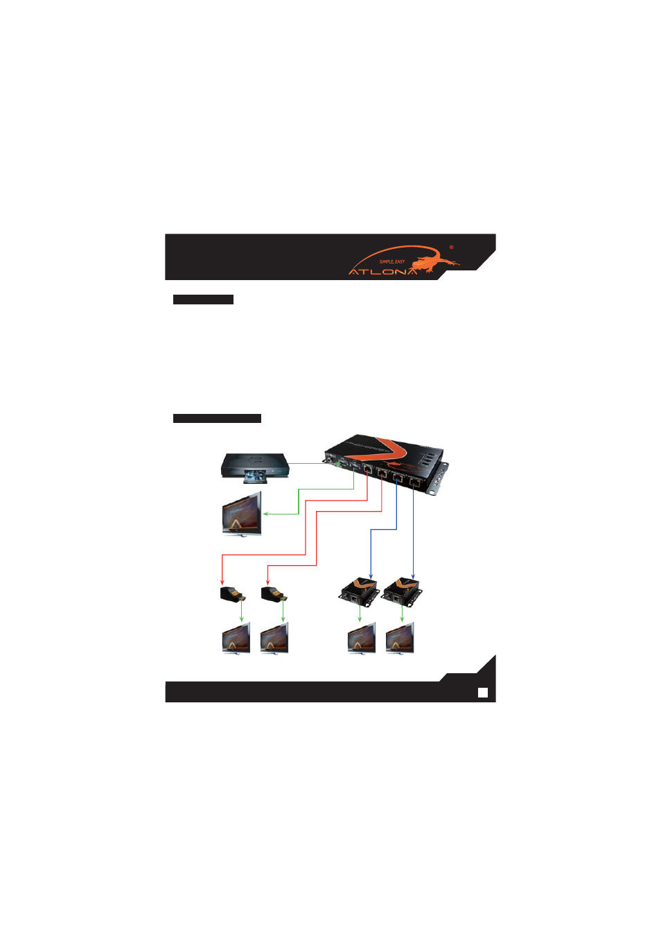
CONNECTION DIAGRAM:
HDTV1
HDMI Cable
AT-HD15SRS
AT-HD15SRS
CAT5 cable up to 25m (80ft)
HDMI cable
CAT5 cable up to 60m (200ft)
AT-HDRS
AT-HDRS
HDMI Cable
HDMI Cable
HDMI Cable
HDMI Cable
HDTV2
HDTV3
HDTV
HDTV4
HDMI source
e
able
AT-HD-V14SS