Operation – ABUS Technologies Field Logger Data Acquisition/Recorder User Manual
Page 15
ABUS TECHNOLOGIES INC.
15
Field
Logger
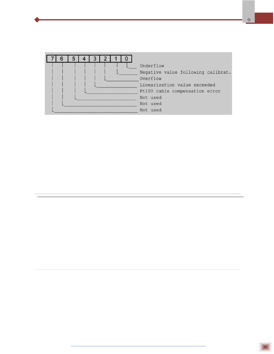
Registers 11 to 14:
Report A/D conversion errors:
Byte High
odd channels:
Byte High to Odd Channel
Byte Low even channels:
*Same as byte high, for the adjacent channel.
7.5.3 Digital Outputs
Field Logger relays can be configured as serial activated digital outputs. The Modbus command
for setting the digital outputs is:
05 – Preset Single Coil
Relay 1 (ALM1 terminals) uses address 0. Relay 2 (ALM2 terminals) uses the address 1.
8. OPERATION
Disconnect mains before wiring the signals to the Field Logger. When turned
on, the Field Logger shows a flashing LED (2 second period) indicating the operating
condition. When in logging mode (in the models with local memory for recording the
readings), the Field Logger LED shows a double flash every 2 seconds. At the end of
the logging period, the LED returns to the single flash. Two other LEDs, Rx and Tx,
signal the activity in the RS485 interface.
Data Logging
The Field Logger detects the specific hardware (memory and real time clock) required for data
logging. If this hardware is present, the parameters in the Acquisition Page will be enabled for
configuration. The software FieldChart was designed to be used with the Field Logger. It performs the
upload of the logged data and executes many other tasks, like on-line monitoring and alarm
visualization.
If third party software packages are aimed, a driver for the Field Logger must be developed.
See in the next section information on the protocol.