ABUS Technologies ATxBlock Temperature Transmitter User Manual
Page 9
ABUS TECHNOLOGIES INC.
9
ATxBlock
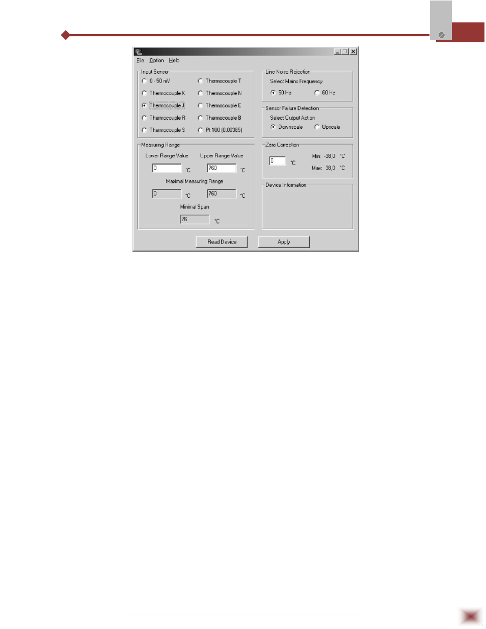
ATxConfig main screen
The fields, in the above ATxConfig main screen, are described as under:
1. Input Sensor: Choose the desired temperature sensor among the available
options.
2. Measuring range: Defines the beginning and the end of the range.
a. Lower Range Value: sets the value of the input signal (temperature or mV)
associated to the 4mA output.
b. Upper Range Value: sets the value of the input signal that will correspond
to the 20 mA output
The values configured in these fields can not be beyond the sensor measuring
range. The minimum span value has to be observed as well (see Table ATxBlock
Input Sensors).
3. Line Noise Rejection: The ATxBlock incorporates a digital filter to cancel the
induced noise from the 50 or 60 Hz systems. For better performance, select the
line frequency used in your country.
4. Sensor Failure Detection: establishes the transmitter output behavior (upscale or
down-scale) in the presence of a sensor fail.
5. Zero Correction: Allows for small sensor corrections.
6. Read Configuration: Brings to the screen the current ATxBlock parameters
configuration.