Configuration – ABUS Technologies ATxBlock Temperature Transmitter User Manual
Page 7
ABUS TECHNOLOGIES INC.
7
ATxBlock
2. The instrument should have its own power supply wires, which should not be shared with electrical
motors, coils, contactors, etc.
3. Installing RC filters is strongly recommended at contactor coils or any other inductors.
4. System failure should always be taken into account when designing a control panel to avoid
irreversible damage to equipment or people.
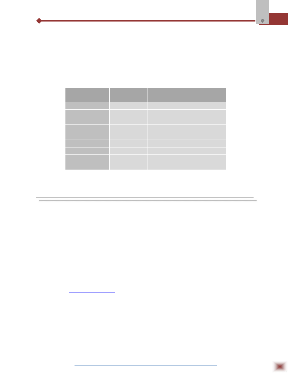
6.2 Input Sensors
SENSOR TYPE
RANGE
MINIMUM MEASUREMENT SPAN
Thermocouple K
0 to 1370 °C
100 °C
Thermocouple J
0 to 760 °C
100 °C
Thermocouple R
0 to 1760 °C
400 °C
Thermocouple S
0 to 1760 °C
400 °C
Thermocouple T
0 to 400 °C
100 °C
Thermocouple N
0 to 1300 °C
100 °C
Thermocouple E
0 to 720 °C
100 °C
Pt100
-200 to 530 °C
40 °C
Voltage
0 to 50 mV
5 mV
ATxBlock Input Sensors
7. CONFIGURATION
Please check the configuration parameters programmed in the ATxBlock, using
the ATxConfig software. A communication path needs to be established between the
ATxBlock and the serial port of a PC. The 1.5 m long ATxConfig Adaptor is provided
for this purpose. Connect its DB9 end to the PC COMM port and the other end to the
transmitter as shown in figure to follow. Once configured, the transmitter is ready to be
installed in the process.
Note: The ATxConfig Adaptor and Software can be purchased separately from ABUS
or one of its distributors. The latest release of this software can be downloaded from
our web site
www.abustek.com
Do not save the ATxConfig software into a file which contains accent marks. To
install, run the ATx_setup.exe and follow the instructions. To install the configurator,
run the ATx_setup.exe file.
Serial port configuration errors may occur when other devices are sharing the
same port (ex.: Palm Hot Sync). Close all serial port applications prior to using the
ATxConfig software.