Belt pack transmitter, Battery insertion, Operating instructions – MIPRO mr515(2ce095) User Manual
Page 6: Parts name and functions
- 9 -
- 1 0 -
1.
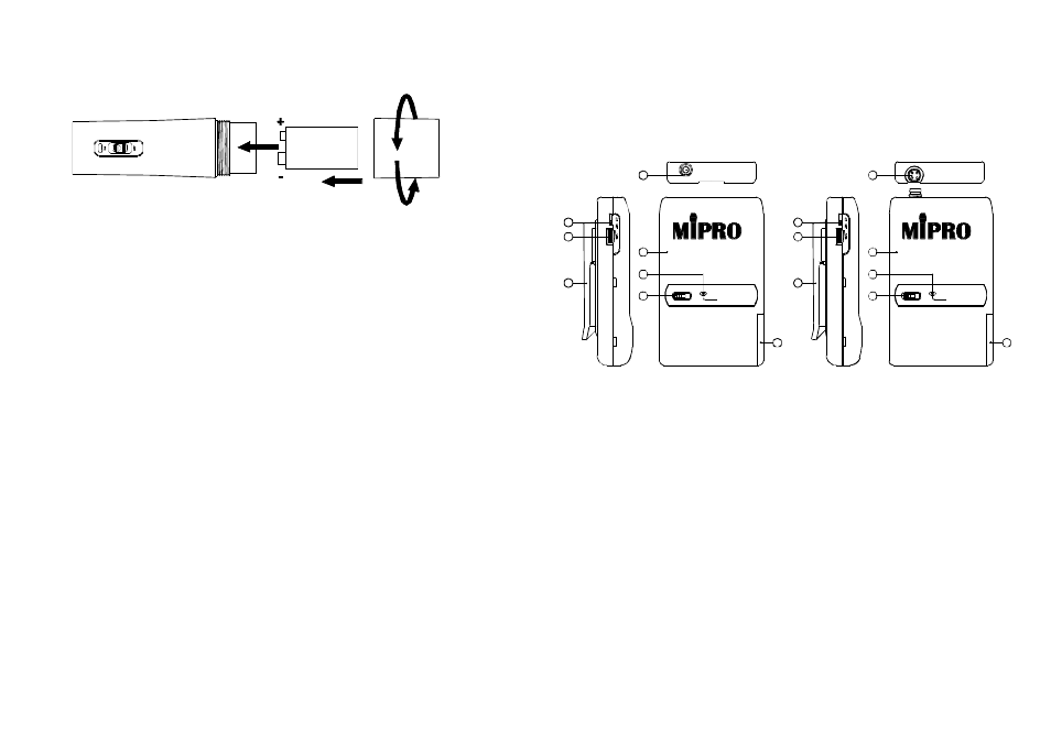
Unscrew batterycap in counter-clockwise direction (6).
2.
Insert a 9V battery into the battery compartment according to the
correct polarity as shown in Fig.2. The moment the battery touches
the terminals o f compartment, the indicator will flash briefly (3).
This means the polarity is correct. However, if no f lash occurs, this
indicates wrong insertion or battery i s dead. Please re-insert the
battery according to its correct polarity or exchange a fresh battery.
1.
When microphone is s witched on:
At the moment of the power i s switched on, the indicator will flash
briefly i ndicating normal operation.
SIGNAL l ed indicator of receiver glows.
The more glows indicate received signal strength is strong.
AUDIO LED on t he receiver willglow with thevolume of the
microphone.
Make sure to turn off the microphone to extend the life span o f
the battery. Remove the battery f rom thebatterycompartment if
microphone is not in use for an extended period to avoid battery
acid leakage and damaging the i nternal PCB andsprings.
(a) When power on:
(b) After power on:
(c) During Usage:
(d) When the microphone is not in use:
1
BATT.LOW
OFF
ON
3
4
7
8
11
9
(PHONE JACK)
MIC
1 0
MIC
2
BATT.LOW
OFF
ON
5
6
7
(4 PIN JACK)
8
9
11
10
1. Battery Insertion
(Fig.2)
2. Operating Instructions
Belt Pack Transmitter
1. Parts Name and Functions
1. Phone JackInput Connector: Connects to phonejack 3.5mm connector.Allow
forlavalier and headset microphones.
2. 4-Pin JackInput Connector: ConnecttoMIPRO4-pinconnector. Allow 5
different input. (See 5 ways of connection on AF Input Connections)
3. Lock level Switch: Whenswitchto upward position, it will f i x a n d locked
volumeatmaximum level making the volumecontrolnow unadjustable. W hen
switch is at downward position,it can freely adjust the audioinput level w ith
thevolume control.
4. Volume C ontrol: Adjusts the audio inputlevel.
5. GT/MT Switch: Switch GT position f o r electricguitarusage ONLY. Gain
Control is irrelevant for
T? Switc h to
T
or conden ser mic rophon e,
G
M
f
wired microphone or Line-in. Gain C ontrol works in
T
or inp ut
M
f
sensitivityadjusting.
6. Gain Control:Adjusts thedesirous inputgain.
7. TransmitterHousing: Packages the PCBand b attery.
8. Battery S tatus Indicator: Indicates the power o n / off and battery status.
(a)When power switch is turnedon: The LED indicator flashes briefly,
indicating normal battery status.
(b)When RED light illuminates at either power onorduringusage: The battery
level islow, therefore, a newbat teryreplacement is thus necessary.