Two 19/2-inch units receiver installation, Installation of the receiver – MIPRO mr515(2ce095) User Manual
Page 3
- 3 -
- 4 -
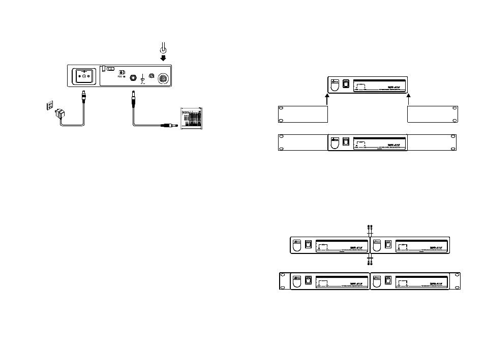
3. Two 19/2-inch units receiver installation
+
-
MIC
AFOUTPUT
A U X
S Q
LEVEL
ANT
1.
Install antenna in rear (1) or atthefront (9). Extend antenna to the
fullest position. see fig. 3.
2.
Connect theAC/DC adapter cable to DC 12VINPUT JACK (5),
then plugthe a dapter unit into an appropriateAC outlet with caution
tothecorrect voltage under both AC outlet and adapter marked, as
shown i n f i g . 3 .
3.
Audio Output Connection:
1.
Single half-rack receiver
(a) Push therack mount ear optional accessory (FB-11) upwardsuntil it is
firmly attached to the receiver.(fig. 4)
POWER
POWER
2.
Dual half-rack receivers
(a) Position the connecting plates between thetop andbottomof thetwo
receivers andtighten. (Fig.5)
(b) Afterjoiningthe 2 receiverstogether, pushthe optional accessory rack
mount ears (FB-12)upwards until they firmly attached tothe receiver.
(Fig. 5)
POWER
POWER
POWER
POWER
2. Installation of the receiver
(Fig.3)
(a) Unbalanced Level Switch (7) SettingPosition: Wheninputsthe
unbalanced output of a receiver into "AUX-IN" input jackof a mixer
or amplifier or "Electric Guitar", switch theLevel Switch (7) to the
right "AUX" position. Low sensitivity mayoccur if switchto thewrong
position.Wheninputsthe unbalancedoutput of a receiver into the
"MIC-IN" input jack of a mixer o r a mplifier, switchthe Level Switch (7)
to the left "MIC" position. Over loaddistortion mayoccurif switch t o
the wrong position. When using electric guitar, don't use "MIC" position
as it may h avegenerated insufficientlevel.
(b) Unbalanced Output: Using audio output cableattached with"PHONE
PLUG" type, connect one andfrom the unbalancedoutputjack (6)of
the receiver, and the other endto the"AUX-IN" input jackof the
amplifier, a s s hown inFig. 3.
(C) Guitar Output: Using audio output cable attached with "PHONE PLUG"
type, unbalanced output jack (6) of a receiver, and the other end tothe
guitar input jack o f a guitar amplifier. Switch the Level Switch (7) to
"AUX"position.
(Fig.4)
(Fig.5)