Belt pack transmitter – MIPRO act707d(2ce150)b User Manual
Page 11
BELT PACK TRANSMITTER
BELT PACK TRANSMITTER
1 8
19
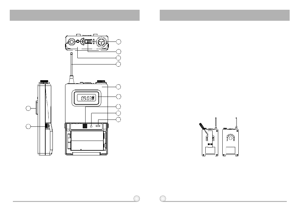
1. PARTS NAMES AND FUNCTIONS
(Fig.1)
1. AF InputJack:Connects to a lavaliere orheadset microphone. (See 5 w ays
ofconnection on AF Input Connections)
2. Power Switch: Tums power "on" and "off"of the transmitter.
3. Battery Status Indicator: Indicates the power on / offand battery status.
(a) When power switch is turnedon: The LEDindicator flashes briefly,
indicating normal battery status.
(b) When RED light illuminates at either power on or duringusage: The
battery levelis low, therefore, a new battery replacement is thus necessary.
4. TransmittingAntenna: 1 / 4
transmitting antenna.
5. Transmitter Housing: Packages the PCB and battery.
6. Functions ofLCD Display
7. ACT Signal Receptor: Receiving ACT signal and adjusting frequency
automatically.
8. Gain Control: Adjusts the desirous inp ut gain.
9. GT/MT Level Selector: Switch GT position forelectric guitar usage and "Line
In". Gain Control is irrelevant for "GT". Switch to "MT" for condenser
microphone or wired microphone. Gain Control works in "MT" forinput
sensitivity adjusting.
10.Battery Compartment andCover: Accommodates two 1.5V(AA) batteries.
11.Detachable Belt Clip: Allows 360 degrees rotating tosuit transmitting angles.
To detach simply use a screwdriver at a 45 degree angle to unfasten. see
diagram.
λ
1
2
11
3
5
8
9
7
4
6
ACT SERIES
GROUP CHANNEL BAT
GAIN
MTGT
10
OFF
ON
BATT.
LOW