Automatic centering sensor adjustment, C. zero c. gain – Nexen Size 18 964102 User Manual
Page 9
9
FORM NO. L-20245-C-1099
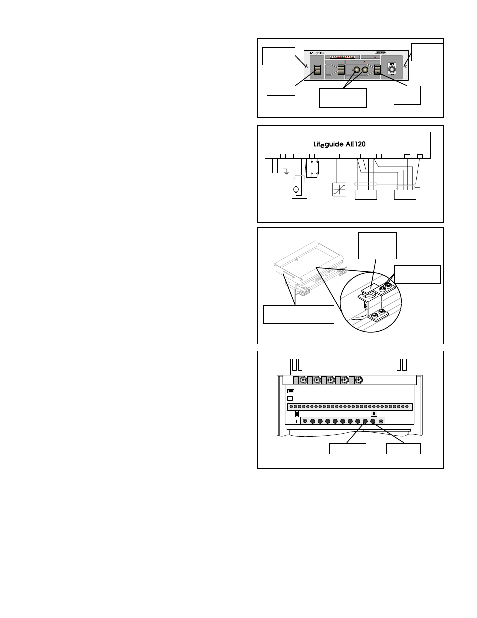
AUTOMATIC CENTERING SENSOR ADJUSTMENT
1.
Remove the two Screws located on the front panel of the
AE120 (See Figure 16).
2.
Slide the AE120 chassis out of the housing.
3.
Set the AE120 Power Switch to ON and set the Mode
Switch to MAN (See Figure 16).
4.
Connect a voltmeter across Terminals 9 and 10 of the
AE120 (See Figure 17).
5.
Using the Manual Push Buttons, center the Roll Base
and verify the edges of the Roll Base and Base are
parallel to each other (See Figures 16 and 18).
6.
Loosen the Socket Head Cap Screws and adjust the
Proximity Sensor Bracket as necessary to obtain a 7.0
volt reading on the voltmeter (See Figure 18); then,
tighten the Socket Head Cap Screws when the adjustment
is complete.
7.
Disconnect the voltmeter from Terminals 9 and 10.
8.
Set the Mode Switch to CENTER (See Figure 16) and
adjust the C. ZERO pot to maintain the Web Guide at its
neutral position (See Figure 19).
9.
If the Web Guide hunts or oscillates back and forth with
the Mode Switch set to CENTER, adjust the C. GAIN pot
until the motion stops (See Figure 19).
FIGURE 16
BR
Extension
Retraction
BL
GN
WH
RD
BK
GN
WH
RD
BK
Power Supply
AC100V~240V
50/60 Hz100VA
Motor
Actuator
Limit
Switch
Auto
Centering
Sensor
Left
Sensor
Right
Sensor
1
M
2 3
4 5
6
7 8
9 10
11 12 13 14 15 16
17
18
FIGURER 17
FIGURE 18
FIGURE 19
MODEL
AE120
MAN
CENTER
AUTO
AUTO
POWER
ON
LEFT
CPC
RIGHT
MAN
Remove
Screw
Remove
Screw
Power
Switch
Manual Push
Buttons
Mode
Switch
Proximity
Sensor
Bracket
Roll Base and Base
must be parallel.
Socket Head
Cap Screws
LAMP
PH B1
GAIN 1
PH B2
GAIN 2
OUTPUT
F. ADJ
C. ZERO C. GAIN
C. ZERO
C. GAIN