Calibration and adjustment, Limit switch adjustment, Ae120 calibration – Nexen Size 18 964102 User Manual
Page 4
4
FORM NO. L-20245-C-1099
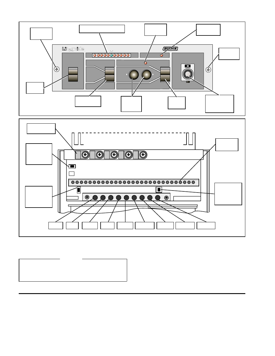
CALIBRATION AND ADJUSTMENT
MODEL
AE120
MAN
CENTER
AUTO
AUTO
POWER
ON
LEFT
CPC
RIGHT
MAN
FIGURE 4
Remove
Screw
Error Indicator Array
Auto
Indicator
End of
Travel LED
Remove
Screw
Mode
Switch
Photo Head
Selector
Power
Switch
Fine
Adjustment
Control
Manual
Push
Buttons
LAMP
PH B1
GAIN 1
PH B2
GAIN 2
OUTPUT
F. ADJ
C. ZERO C. GAIN
Strain Relief
Clamps
NOR/REV
Switch for
Center
Operation
NOR/REV
Switch for
Auto
Operation
LAMP PHB1 GAIN 1 PHB2 GAIN 2 OUTPUT F. ADJ. C.ZERO C. GAIN
Terminal
Block
NOR/REV
Switch for
Manual
Operation
FIGURE 5
LIMIT SWITCH ADJUSTMENT
CAUTION
The Limit Switches have been set by Nexen for
maximum travel. If travel limitation is necessary, refer
to MAINTENANCE (Page 7) for Limit Switch Adjustment.
AE120 CALIBRATION
1.
Remove the two Screws located on the front panel of the
AE120 (See Figure 4).
2.
Slide the AE120 chassis out of the housing to allow
access to the Terminal Block (See Figure 5).