Operation, Edge position control (epc), Center position control (cpc) – Nexen Size 18 964102 User Manual
Page 6
6
FORM NO. L-20245-C-1099
OPERATION
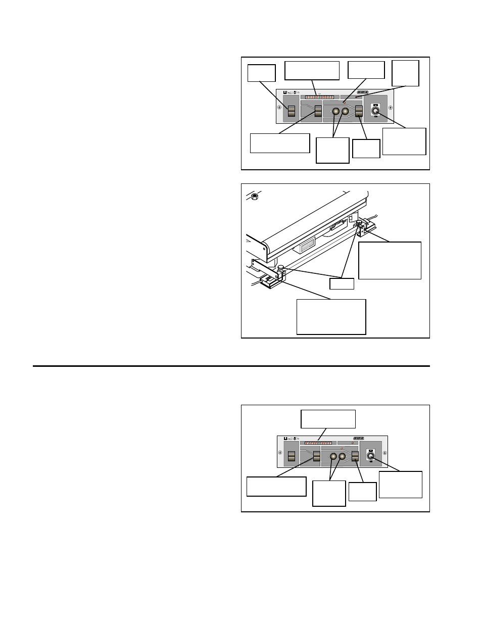
Edge Position Control (EPC)
1.
Set the Mode Switch to CENTER (See Figure 6).
2.
Set the Fine Adjustment Control to 5.00 (mid-travel)
(See Figure 6).
3.
Thread the web into the machine.
4.
Set the Photo Head Selector Switch to LEFT or RIGHT
as appropriate (See Figure 6).
5.
Set the Mode Switch to MAN (See Figure 6).
6.
Operate the machine at slow speed.
7.
Using the Manual Push Buttons, align the web to the
centerline of the machine (See Figure 6).
8.
Loosen either the right or left Knob (depending on which
Photo Head was selected in Step 4) and move the right
or left Photo Head, Bracket, and Sensor Bracket Mounting
Block to the edge of the web until the center green light
on the Error Indicator Array glows (See Figures 6 and 7);
then, tighten the Knob to secure the Photo Head.
9.
Set the Mode Switch to AUTO (See Figure 6).
10. Accelerate the machine. The web should remain in the
center of the Photo Head and the green light on the Error
Indicator Array should stay on.
11. If the web is misaligned with the centerline of the machine,
it can be moved with the Fine Adjustment Control located
on the control panel (plus or minus 0.20" [5 mm] (See
Figure 6).
MODEL
AE120
MAN
CENTER
AUTO
AUTO
POWER
ON
LEFT
CPC
RIGHT
MAN
FIGURE 6
FIGURE 7
Center Position Control (CPC)
1.
Set the Mode Switch to CENTER (See Figure 8).
2.
Set the Fine Adjustment Control to 5.00 (mid-travel)
(See Figure 8).
3.
Thread the web into the machine.
4.
Set the Mode Switch to MAN (See Figure 8).
5.
Operate the machine at slow speed.
6.
Using the Manual Push Buttons, align the web with the
centerline of the machine.
7.
Set the Photo Head Selector Switch to LEFT (See Figure
8).
8.
Loosen the left Knob and move the left Photo Head,
Bracket, and Sensor Bracket Mounting Block to the edge
of the web until the center green light on the Error
Indicator Array glows (See Figures 8 and 9); then,
tighten the Knob to secure the Photo Head.
MODEL
AE120
MAN
CENTER
AUTO
AUTO
POWER
ON
LEFT
CPC
RIGHT
MAN
FIGURE 8
Power
Switch
Error Indicator
Array
Photo Head
Selector Switch
Manual
Push
Buttons
Fine
Adjustment
Control
Auto
Indicator
End of
Travel
LED
Mode
Switch
Left Photo Head,
Bracket, and
Sensor Bracket
Mounting Block
Right Photo Head,
Bracket, and
Sensor Bracket
Mounting Block
Knob
Photo Head
Selector Switch
Manual
Push
Buttons
Fine
Adjustment
Control
Mode
Switch
Error Indicator
Array