Connection diagrams – Nexen RSTC1000 964523 User Manual
Page 5
FORM NO. L-21208-C-0908
2
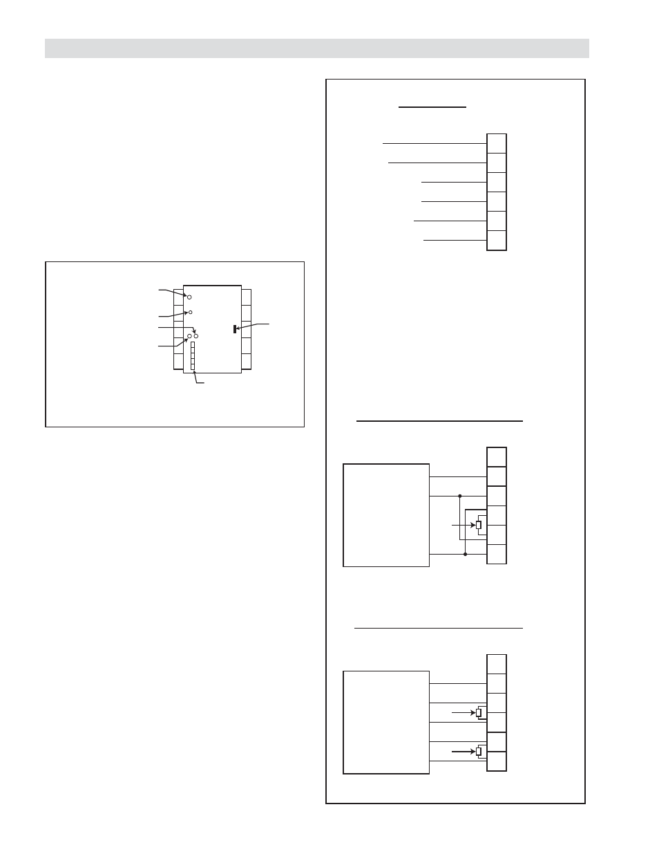
CONNECTION DIAGRAMS
Modbus RS485 Port: This port is for communicating
with the RSTC1000 using the Modbus RTU protocol
over a 2-wire or 4-wire RS485 physical layer (Refer to
Figure 1).
Communication Indicator: Yellow indicator, visible
through top cover, will illuminate whenever the
RSTC1000 communicates over the RS485 port.
Communication Error Indicator: Red indicator,
visible through top cover, will illuminate whenever the
RSTC1000 detects an error with a received message.
Figure 1
Modbus RS485 Connections
DC Common
TxB+
TxA–
RxB+
RxA–
1
2
3
4
5
6
DC Common
RxB+
RxA–
TxB+
TxA–
LTR
RSTC1000
PLC or HMI
Four Wire RS485 Connections
LTR
DC Common
TxB+
TxA–
RxB+
RxA–
1
2
3
4
5
6
DC Common
Non-Inverted Tx/Rx
Inverted Tx / Rx
RSTC1000
PLC or HMI
Two Wire RS485 Connections
+24 VDC
DC Common
TxB+
TxA–
RxB+
RxA–
1
2
3
4
5
6
Red
Black
White (RxB+)
Yellow (RxA–)
Blue (TxB+)
Orange (TxA–)
RSTC
ROP
ROP - RSTC
LTR
Termination resistors added externally
- Recommend 150
Ω, 0.5 W
LTR = User supplied line termination resistor
Cable Recommendation:
-
Shielded
- 24 awg is always suffi cient
- 4 wire system, 1000 m (9600 baud)
- 2 wire system, 500 m (9600 baud)
Figure 2
RSTC1000
R
S
T
C1000
USB
RS485
Power Indicator
Reset
Communication Error
Indicator
Communication Indicator