Installation, Electrical connections, Caution – Nexen MB25B 911996 User Manual
Page 6
FORM NO. L-20127-L-0513
6
Use 16 Ft. [5 m] cables provided with MB Tension Sen-
sors to make connections with Tension Controller, Tension
Amplifier or Tension Meter.
NOTE
If you are using a Nexen controller, refer to the
appropriate instruction manual. For all other
controllers, see Figure 9.
Cables may be extended up to 500 Ft. [156 m] with
customer supplied four conductor 18 AWG shielded
cable. Be certain to maintain continuity of shield when
splicing cable. Longer cables (30, 50, 75, and 100 Ft.)
are available from Nexen if an unspliced cable is required
(See REPLACEMENT CABLE ASSEMBLIES).
NOTE
When using MB05, MB11, or MB25 in reverse
wrap, switch yellow or white and green wires at the
Tension Controller or Tension Meter (See appropriate
instruction Manual).
• Sensor Roll span must equal sensor span. This is
achieved by securing the MB Tension Sensor to the
mounting surface, then the Pillow Block Bearings to
the MB Tension Sensors, and finally the bearings to
the Sensor Roll shaft (See Figure 7).
• When MB Tension Sensors are mounted to a base
of material different than that of the Sensor Roll, i.e.,
aluminum roll, steel mounting base; secure only one
Pillow Block Bearing to the roll shaft. This will allow
for different rates of thermal expansion (See Figure 7).
• Mounting surfaces must be parallel to one another.
Self centering Pillow Block Bearings are required to
take up any variations in parallelism (See Figure 8).
• MB05 is normally mounted using the sidewall
mounting plate and cap screws provided.
•
A side wall mounting bracket for the MB11 is available
from Nexen. The part number is 31084.
INSTALLATION
(continued...)
FIGURE 7
Sensor Span
Sensor Roll
Sensor Roll Span
Set
Screw
Pillow Block
Bearing
Set
Screw
MB
T
ension
Sensor
FIGURE 8
MB
T�ension
Sensor
Inclinationof
DetectorMounting
Surface
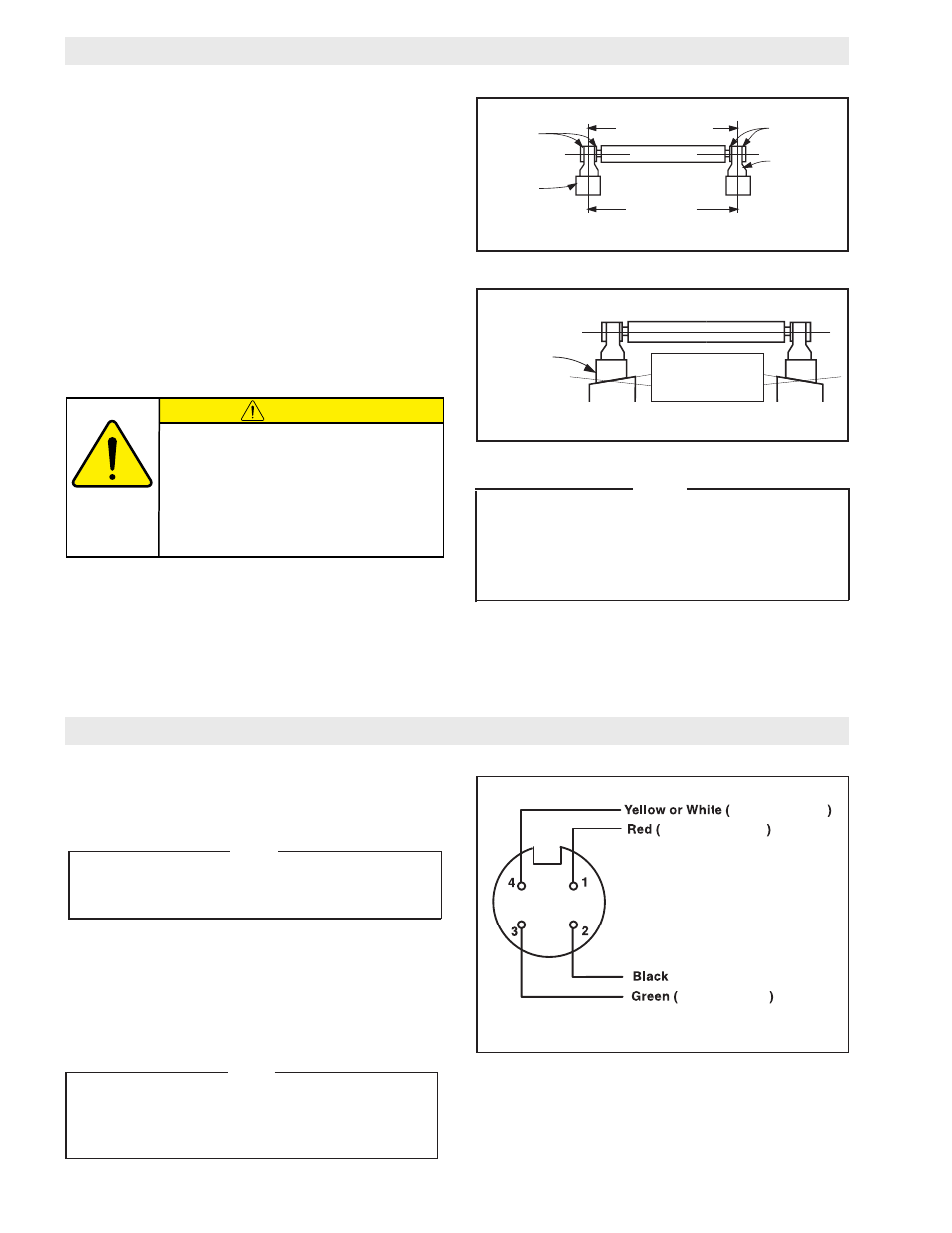
ELECTRICAL CONNECTIONS
FIGURE 9
FRONT VIEW OF CONNECTOR
Signal
(Excitation Common)
Signal Common
+6VDC Excitation
+400mV
NOTE
Due to the high forces generated, a side wall
mounting bracket is not recommended for MB
Tension Sensors MB33 and MB41. Mount these
MB Tension Sensors to a rigid horizontal or near
horizontal surface.
CAUTION
Non-compliance with the above conditions
will induce heavy side loads within the MB
Tension Sensor. This will cause hysteresis,
and the MB Tension Sensor will measure
mechanical resistance rather than tension
load. In extreme cases it will mechanically
damage the MB Sensors.