Electrical connections adjustment – Nexen DPS30 964517 User Manual
Page 6
FORM NO. L-21260-A-1107
6
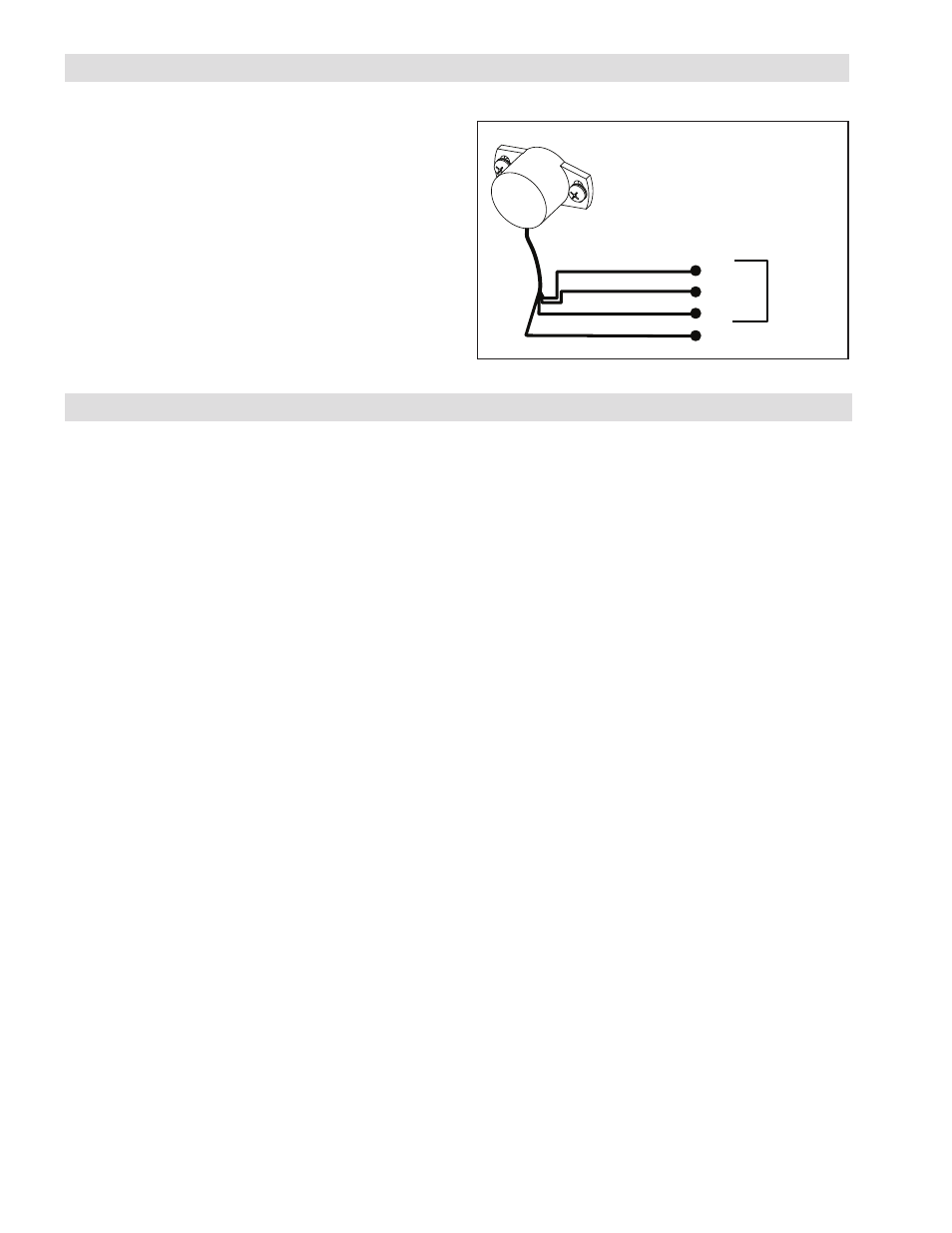
+24 VDC
SHIELD WIRE
BROWN
WHITE
GREEN
SIGNAL
DANCER
POSITION
CONTROLLER
COM
EARTH GROUND
Figure 6
1. Route the Dancer Position Sensor signal cable
through the machine.
2. Connect the signal cable to a controller (See Figure
6).
NOTE: The shield wire from the signal cable should
be earth grounded at the controller.
If noise is still present on the position signal, ensure
the sensor shaft has a low impedance connection to
earth ground through the machine frame.
ELECTRICAL CONNECTIONS
ADJUSTMENT
1. Apply power to the Dancer Position Sensor.
2. Refer to Installation for the proper alignment of the
sensor.
3. Using a voltmeter, measure the voltage across the
green (+) and brown (-) wires (See figure 6). The
voltage reading must match the supply voltage for
proper operation (See Specifications).
4. Measure the sensor output voltage across the white
(+) and brown (-) wires. With the dancer arm held
in its mid travel position, the sensor output should
be approximately +5 VDC. If it is not, then slightly
loosen the sensor’s fasteners and rotate the sensor
until the voltage reading is +5 VDC.
5. Tighten the fasteners securely to prevent the sensor
from moving.
6. Move the dancer arm through its full range of mo-
tion and check that the voltage changes between
0 and 10 VDC. If the output voltage stops chang-
ing as the dancer arm is moving, slightly loosen the
sensor’s fasteners and rotate the sensor. If this
persists, the angular movement of the dancer arm
might exceed the measurement range for the sensor
(See Specifications).
7. Trim back any unused wires to prevent electrical
shorting problems.
8. At this time the installation and adjustment of the
dancer position sensor is complete. Refer to the
controller manual for any further setup and calibra-
tion procedures.