Nexen DPS30 964517 User Manual
Page 5
5
FORM NO. L-21260-A-1107
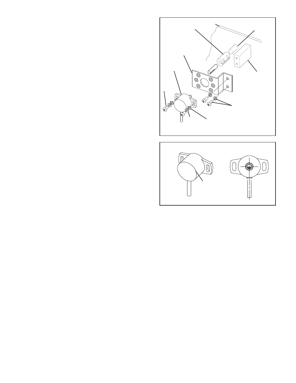
1. Purchase a zero backlash flexible shaft coupler that
accommodates the diameter of the sensor shaft
(Item 1) on one end and the dancer arm pivot shaft
on the other end (See Figures 4 and 7).
2. Slide the shaft coupler onto the dancer arm pivot
shaft, inserting the shaft no further than half the
thickness of the coupler clamp; then, tighten the
clamp around the shaft (See Figure 4).
3. The orientation of the Dancer Position Sensor (Item
1) must be as shown in order to match the mid out-
put of the Dancer Position Sensor to the mid travel
position of the dancer arm (See Figure 5).
4. Attach Dancer Position Sensor (Item 1) to one of
the three hole configurations on the Bracket (Item 3)
with the two shorter Pan Head Screws (Item 4), Flat
Washers (Item 6), and Lock Washers (Item 5) (See
Figure 4).
5. Hand tighten the screws just enough to prevent
sensor from moving during installation (See Figure
4).
6. Slide the Dancer Position Sensor (Item 1) into the
coupling (See figure 4).
7. Measure the distance from the bottom of the Brack-
et (Item 3) to the machine’s side frame. Fabricate a
spacer block to make up the distance between the
Bracket and the machine’s side frame (See Figure
4).
8. Slide the Dancer Position Sensor (Item 1) into the
coupling again with the spacer block in place on the
machine’s side frame and mark the location for the
bracket’s two mounting holes.
9. Remove the Dancer Position Sensor (Item 1)
and Bracket (Item 3); then, drill and tap two 8-32
threaded holes centered within the marks drawn in
Step 8.
10. With the dancer arm held firmly in its mid travel
position, slide the Dancer Position Sensor (Item 1)
into the coupling again making sure the sensor shaft
marking is pointing toward the cable.
Insert the shaft no further than half the thickness of
the coupling clamp.
Mid-Point of Output
when viewed from Front
Front
Back
Figure 5
Figure 4
Dancer
Arm
Pivot
Shaft
Machine
Frame
Coupling
Spacer
block
COUPLING CONNECTION
Customer supplied
Screws and
Lock Washers.
1
11. Tighten the clamp around the sensor shaft (See
Figure 4).
12. Using customer supplied 8-32 screws and lock
washers, secure the Bracket (Item 3) to the cus-
tomer supplied spacer block and the machine’s side
frame (See Figure 4).
3
5
6
1