Introduction installation – Nexen DPS60 964518 User Manual
Page 4
FORM NO. L-21261-B-0214
4
INTRODUCTION
INSTALLATION
Nexen Dancer Position Sensors have been designed to accurately measure the rotational movement of a dancer arm.
This family of sensors use Hall Effect technology which provide for benefits such as infinite resolution, low drag, and
no mechanical wear. They are ideally suited to work with Nexen’s Dancer Position Controllers.
NOTE: Mounting of the Dancer Position Sensor can
be accomplished two ways. The first is the Direct
Connection method and the second is the Coupling
Connection method. Review the instructions for both
methods and select the method best suited for your
application.
NOTE: For serial number prior to 2269020, refer to
Literature 21260.
DIRECT CONNECTION
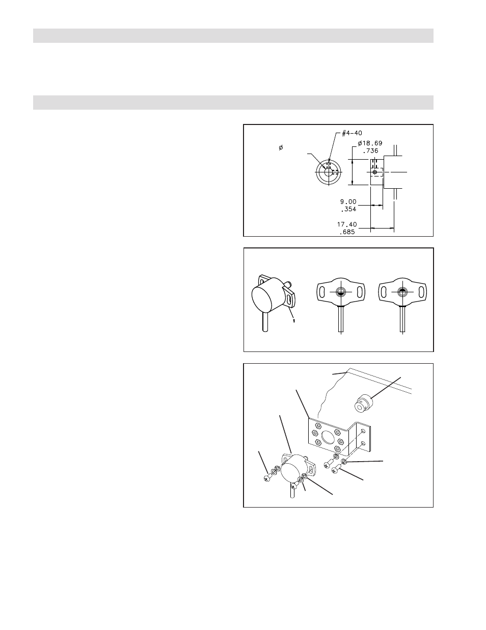
1. Verify that the dancer arm pivot shaft’s end complies
with the dimensions given (See Figure 1).
2. Drill and tap two 4-40 threaded holes 90° apart for
two, .25” set screws.
3. The orientation of the Dancer Position Sensor (Item1)
must be as shown in order to match the mid output of
the Dancer Position Sensor to the mid travel position
of the dancer arm (See Figure 2). The DPS60A Dual
sensor has two measurement ranges allowing for
flexibility in the mounting position (See Figure 7).
4. Attach Dancer Position Sensor (Item 1) to one of the
three hole configurations on the Bracket (Item 3) with
two shorter Pan Head Screws (Item 4), Flat Washers
(Item 6), and Lock Washers (Item 5). (See Figure 3).
5. Hand tighten the screws just enough to prevent it from
moving during installation (See Figure 3).
6. Slide the Dancer Position Sensor (Item 1) into the shaft
until the Bracket (Item 3) contacts the machine’s side
frame (See Figure 3).
7. Mark the location of the Bracket’s two mounting
holes.
8. Remove the Dancer Position Sensor (Item 1) and
Bracket (Item 3); then, drill and tap two 8-32 threaded
holes centered within the marks drawn in Step 7.
9. With the dancer arm held firmly in its mid travel
position, slide the Dancer Position Sensor (Item 1) into
the shaft while making sure the sensor shaft marking
is pointing toward the cable (See Figure 3).
Figure 1
Figure 3
Dancer
Arm
Pivot
Shaft
3
4
5
7
5
6
Machine
Frame
1
+.10
-.00
6.00
+.004
-.000
.236
min.
10. Using the two set screws, secure the dancer pivot
shaft to the sensor shaft by tightening the screws
evenly.
11. Using the two longer Pan Head Screws (Item 7) and
Lock Washers (Item 5), secure the Bracket (Item 3)
to the machine’s side frame (See Figure 3).
Figure 2
Midpoint of
output when
viewed from front.
Alternative
midpoint of
output.
Back
Front