Parts replacement (continued), Caution – Nexen STB600 927239 User Manual
Page 10
10
FORM NO. L-20300-C-0511
B
C
A
B
C
A
3
25
1
5
11
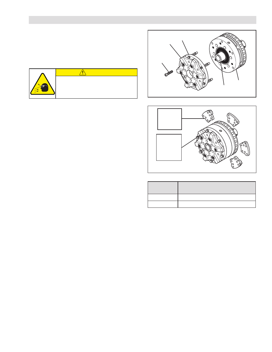
FIGURE 11
TABLE 4
Friction
Facing
Assembly
(Item 4)
Finger Nut
(Item 32)
on
Facing Pin
(Item 7)
FIGURE 12
B
C
A
B
C
A
22. Align the outer race of the new Ball Bearing (Item 22)
with the bearing bore of the Piston Guide (Item 11);
then, press the new Ball Bearing (Item 22) into place.
23. Support the inner race of the new Ball Bearing (Item
22); then, press the Hub/Rotor (Item 5) into the new
Ball Bearing (Item 22) and Piston Guide (Item 11).
24. Reinstall the Retaining Ring (Item 21).
25. Slide the Endcap (Item 3) and Cylinder (Item 1) onto
the Hub/Rotor (Item 5) and Piston Guide (Item 11).
26. Apply a drop of Loctite
®
242 to the threads of the six
Socket Head Cap Screws (Item 25) and secure the
Endcap (Item 3) and Cylinder (Item 1) to the Piston
Guide (Item 11).
27. Alternately and evenly tighten the six Socket Head Cap
Screws (Item 25) to the recommended torque (See
Table 4).
28. Pull out the Finger Nut (Item 32) of the Facing Pin (Item
7) and slide a new Friction Facing Assembly (Item 4)
into the STB.
29. Release the Finger Nut (Item 32) allowing the Facing
Pin (Item 7) to lock the new Friction Facing Assembly
(Item 4) into place.
30. Repeat Steps 28 and 29 until all six of the Friction
Facing Assemblies (Item 4) have been reinstalled.
PARTS REPLACEMENT (continued)
MODEL
RECOMMENDED TORQUE SOCKET
HEAD CAP SCREWS (ITEM 26)
STB 600
45 In. Lbs. [5.1 Nm]
STB 940
143 In. Lbs [16.2 Nm]
CAUTION
Working with spring loaded or tension
loaded fasteners and devices can cause
injury. Wear safety glasses and take the
appropriate safety precautions.