Air line connections, Lubrication, Lubricator drip rate settings – Nexen DFC-1650 964161 User Manual
Page 3
3
FORM NO. L-20272-E-1199
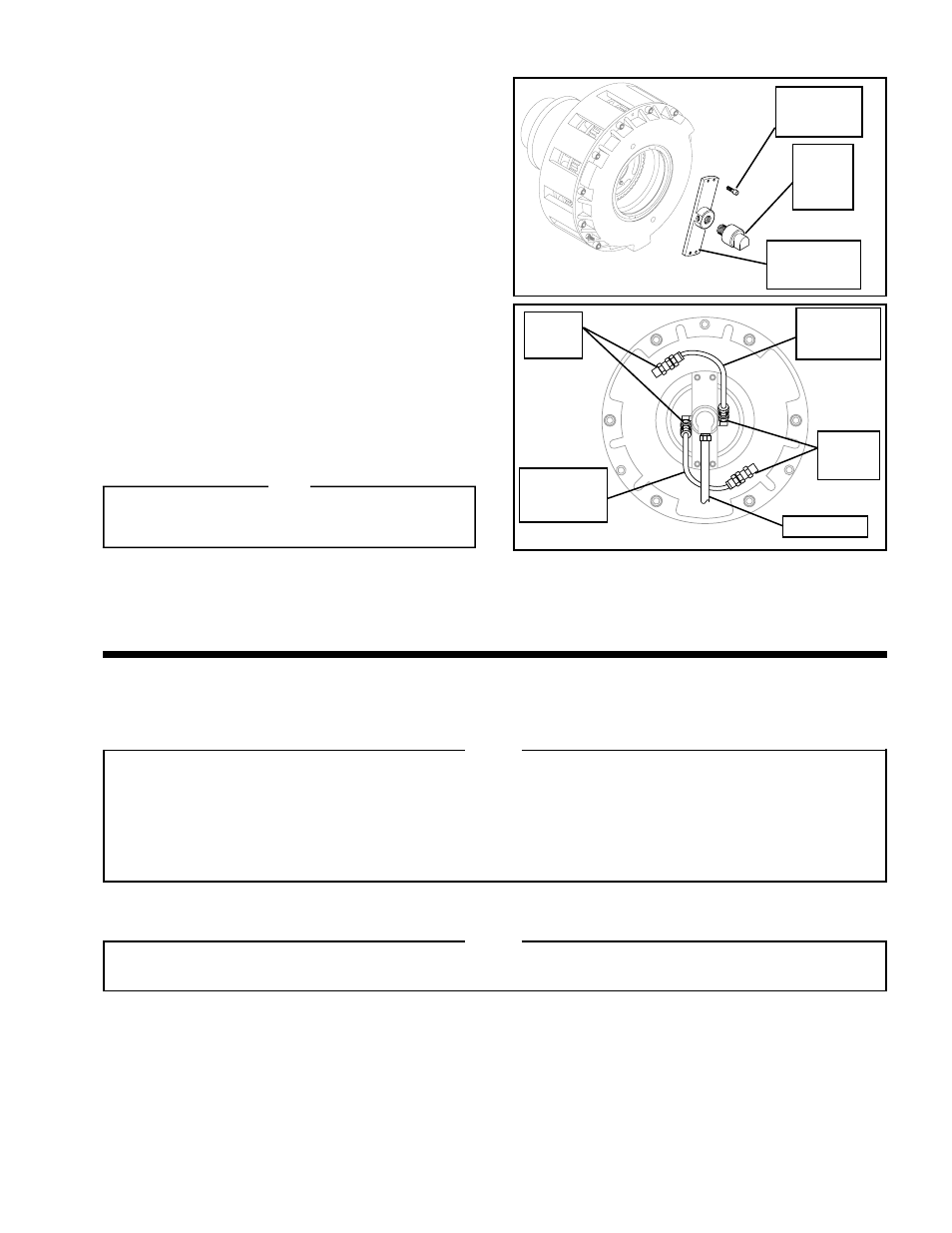
AIR LINE CONNECTIONS
1.
If the Rotary Air Union (Item 30) and Rotary Air Union
Bracket (Item 28) are not assembled, apply pipe
sealant to the threads of the Rotary Air Union and
screw the Rotary Air Union into the Rotary Air Union
Bracket (See Figure 4).
2.
Apply a drop of Loctite
®
242 to the threads of the four Socket
Head Cap Screws (Item 29) provided with the Rotary Air
Union (Item 30) and Rotary Air Union Bracket (Item 28);
then, secure the Rotary Air Union and Rotary Air Union
Bracket to the clutch (See Figure 4).
3.
Tighten the four Socket Head Cap Screws (Item 29) to
5.5 Ft. Lbs. [7.45 N•m] torque (See Figure 4).
4.
Apply pipe sealant to the threads of the Elbow Fittings
and install the Elbow Fittings into the Cylinder of the
clutch and Rotary Air Union (See Figure 5).
5.
Connect the two Hose Assemblies (Item 31) to the
four Elbow Fittings (Item 35) (See Figure 5).
6.
Connect Air Line to the Rotary Air Union (See Figure 5).
NOTE
Air Line must be routed as shown (See Figure 5).
Do not use rigid pipe or tubing for air lines.
FIGURE 4
Elbow
Fittings
(Item 35)
Elbow
Fittings
(Item 35)
FIGURE 5
LUBRICATION
NOTE
Pneumatically actuated devices require clean, pressure regulated, and lubricated air for maximum performance
and long life. The most effective and economical way to lubricate Nexen Clutches and Brakes is with an Air Line
Lubricator, which injects oil into the pressurized air, forcing an oil mist into the air chamber.
Locate the lubricator above and within ten feet of the Clutch or Brake, and use a low viscosity oil such as SAE-10.
Synthetic lubricants are not recommended.
Socket Head
Cap Screw
(Item 29)
Rotary
Air
Union
(Item 30)
Rotary Air
Union Bracket
(Item 28)
LUBRICATOR DRIP RATE SETTINGS
NOTE
These settings are for Nexen supplied lubricators. If you are not using a Nexen lubricator, calibration must
replicate the following procedure.
1.
Close and disconnect the air line from the unit.
2.
Turn the Lubricator Adjustment Knob clockwise three
complete turns.
3.
Open the air line.
4.
Close the air line to the unit when a drop of oil forms in
the Lubricator Sight Gage.
5.
Connect the air line to the unit.
6.
Turn the Lubricator Adjustment Knob counterclockwise
until closed.
7.
Turn the Lubricator Adjustment Knob clockwise one-
third turn.
8.
Open the air line to the unit.
Hose
Assembly
(Item 31)
Hose
Assembly
(Item 31)
Air Line