Caution – Nexen BCB-275 826001 User Manual
Page 10
7
FORM NO. L-20106-E-1209
PARTS REPLACEMENT (continued)
REFER TO FIGURES 4-9.
13. Clean the bearing bore of the Piston (Item 2) with
fresh safety solvent, making sure all old Loctite
®
residue is removed.
14. Apply an adequate amount of Loctite
®
680 to evenly
coat the outer race of the new Ball Bearing (Item 9).
15. Supporting the Piston (Item 2) and pressing on the
outer race of the new Ball Bearing (Item 9), press the
new Ball Bearing into the Piston.
16. Reinstall the Retaining Ring (Item 13).
17. Clean the o-ring grooves and o-ring contact surfaces
of the Piston (Item 2) and Cylinder (Item 4) with fresh
safety solvent and lubricate the o-ring grooves and
contact surfaces with fresh o-ring lubricant.
18. Lubricate the new O-ring Seals (Items 14 and 15
and install the new O-ring Seals onto the Piston
(Item 2) and Cylinder (Item 4); then, slide the Piston
back into the Cylinder.
19. Support the inner race of the new Ball Bearing (Item
9) and press the new Friction Facing/Drive Disc
Assembly (Item 5) into the Cylinder (Item 4), Piston
(Item 2), and new Ball Bearing (Item 9).
20. Reinstall the Retaining Ring (Item 11).
21. Remove the Retaining Ring (Item 12) from the Air
Chamber Housing (Item 3).
22. Press the old Ball Bearing (Item 8) out of the Air
Chamber Housing (Item 3).
23. Clean the bearing bore of the Air Chamber Housing
(Item 3) with fresh safety solvent, making sure all old
Loctite
®
residue is removed.
24. Apply an adequate amount of Loctite
®
680 to evenly
coat the outer race of the new Ball Bearing (Item 8).
25. Supporting the Air Chamber Housing (Item 3) and
pressing on the outer race of the new Ball Bearing
(Item 8), press the new Ball Bearing into the Air
Chamber Housing.
26. Re-install the Retaining Ring (Item 12).
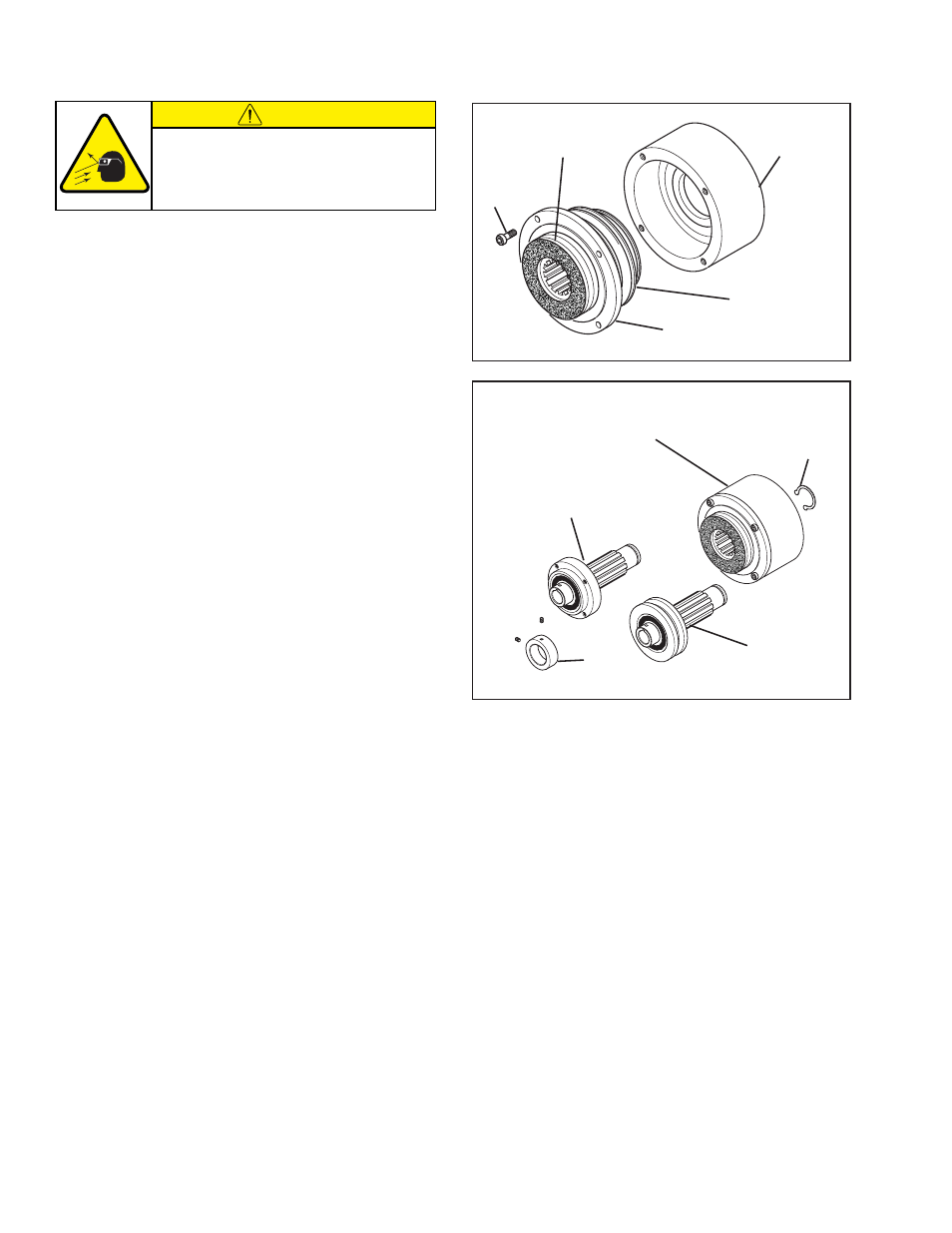
FIGURE 8
FIGURE 9
16
Friction Facing/Drive Disc
Assembly
(Item 5)
Cylinder (Item 4)
Piston (Item 2)
Air Chamber
Housing (Item 3)
Hub (Item 1)
and
Sheave (Item 18)
Hub (Item 1) and
Pilot Mount Drive Disc
(Item 7)
Friction Facing/Drive Disc Assembly (Item 5),
Cylinder (Item 4), Piston (Item 2), and
Air Chamber Housing (Item 3)
6
10
27. Slide the Friction Facing/Drive Disc Assembly (Item
5), Cylinder (Item 4), and Piston (Item 2) into the Air
Chamber Housing (Item 3).
28. Apply a drop of Loctite
®
242 to the threads of the
four Socket Head Cap Screws (Item 16); then,
using the four Socket Head Cap Screws, secure
the Friction Facing/Drive Disc Assembly (Item 5),
Cylinder (Item 4), and Piston (Item 2) to the Air
Chamber Housing (Item 3).
29. Alternately and evenly tighten the four Socket Head
Cap Screws (Item 16) to 66 in-lbs [7.4 Nm].
30. Press the Hub (Item 1) and Pilot Mount Drive Disc
(Item 7) or Sheave (Item 18) back into the Friction
Facing/Drive Disc Assembly (Item 5), Cylinder (Item
4), Piston (Item 2), & Air Chamber Housing (Item 3).
31. Reinstall the Retaining Ring (Item 10); then, slide the
Hub Collar (Item 6) back onto the Hub (Item 1).
CAUTION
Working with spring loaded or tension
loaded fasteners and devices can cause
injury. Wear safety glasses and take the
appropriate safety precautions.