Nexen 8K 845200 User Manual
Page 5
2
FORM NO. L-20013-K-0210
INSTALLATION
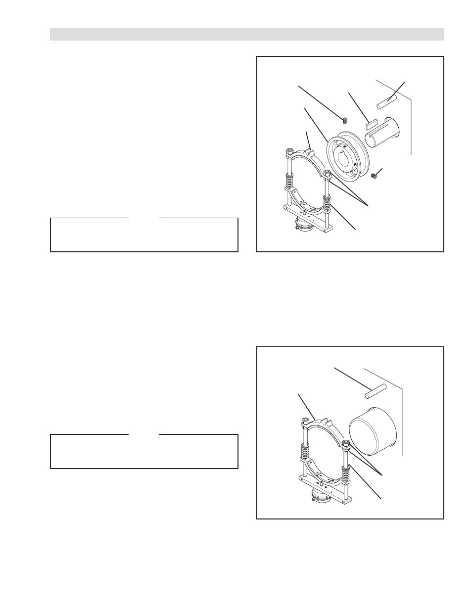
FIGURE 1
BRAKE WITH OPTIONAL DRUM
REFER TO FIGURE 1.
1. Insert a customer supplied Key onto the shaft.
2. Slide the optional Drum over the customer supplied
Key and onto the shaft.
3. Secure the optional Drum to the shaft using two
customer supplied Set Screws.
4. Position the Diaphragm Brake on the optional Drum.
5. Using a customer supplied Holding Pin, secure
the Diaphragm Brake in place with the Holding Pin
passing through the slot in the Diaphragm Brake.
NOTE
Allow sufficient clearance between the Friction
Facings (Item 3) and the optional Drum to allow
free rotation of the Drum.
6. Adjust the Fixed Shoe (Item 1) by loosening the Jam
Nuts (Item 12).
7. Tighten the Jam Nuts (Item 12).
BRAKE WITHOUT OPTIONAL DRUM
REFER TO FIGURE 2.
1. Position the Diaphragm Brake on the shaft.
2. Using a customer supplied Holding Pin, secure
the Diaphragm Brake in place with the Holding Pin
passing through the slot in the Diaphragm Brake.
NOTE
Allow sufficient clearance between the Friction
Facings (Item 3) and the shaft to allow free
rotation of the shaft.
3. Adjust the Fixed Shoe (Item 1) by loosening the Jam
Nuts (Item 12).
3. Tighten the Jam Nuts (Item 12).
FIGURE 2
Customer
Supplied
Key
Optional Drum
Customer Supplied
Set Screw
8K or 12K
Diaphragm Brake
Holding
Pin
Customer Supplied
Set Screw
Fixed Shoe
(Item 1)
Jam Nut
(Item 12)
Holding Pin
8K or 12K
Diaphragm Brake
Jam Nut
(Item 12)
Fixed Shoe
(Item 1)