Installation (continued) – Nexen DBSE 835030 User Manual
Page 6
6
FORM NO. L-20017-C-1212
5. Insert the pull-up bolts and alternately and evenly tighten
them to 15 ft–lb [20.3 Nm] torque.
6. To remove the Q.D. Bushing, remove the pull-up bolts
and reinsert them into the threaded holes of the Q.D.
Bushing. Tighten the pull-up bolts to push out the Q.D.
Bushing.
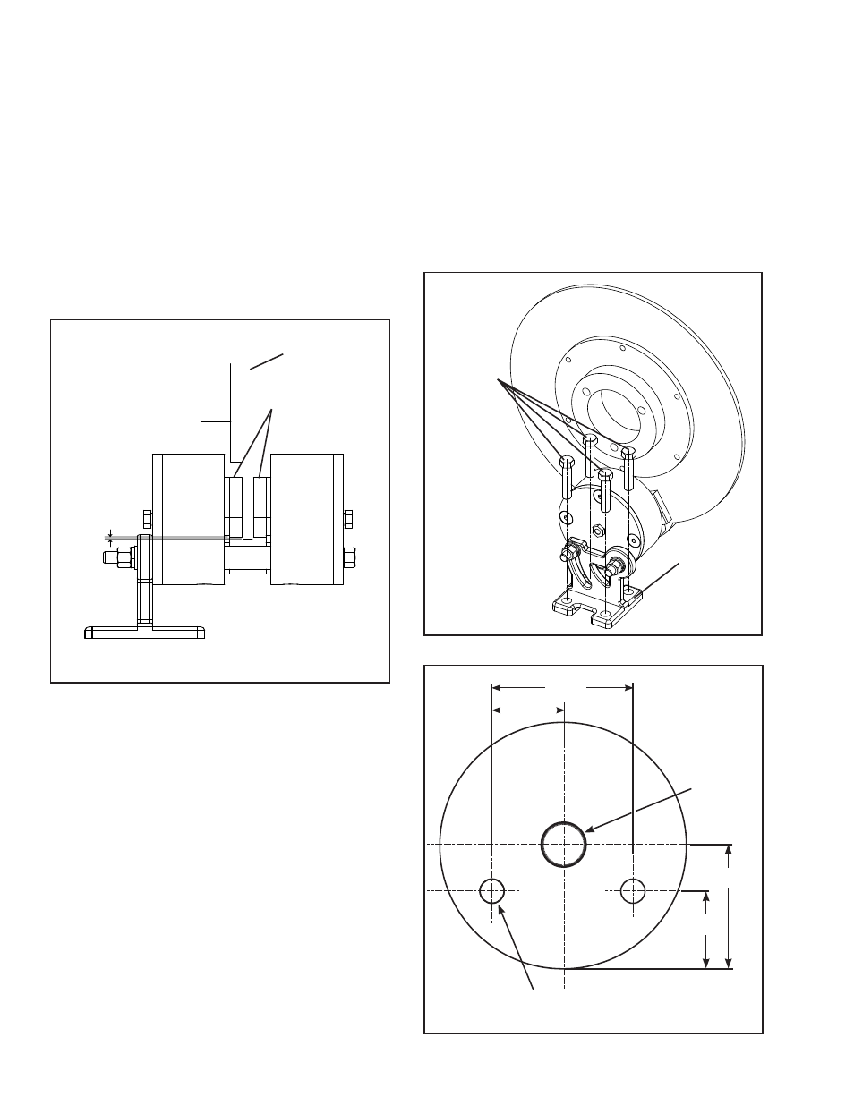
7. Mount the Caliper Brake so the radius of the Disc runs
approximately 0.06 in [1.6 mm] below the outside radius
of the Friction Facing Assembly (Item 1), and with an
equal distance between the Disc and Friction Facing
Assemblies (See Figure 3).
0.06
FIGURE 3
Brake Disc
Friction Facing
Assemblies
(Item 1)
FIGURE 4
Customer
supplied 3/8"
bolts
"T" Support
(Item 12)
8. Use customer-supplied 3/8 in. bolts to mount the "T"
support (Item 12) to a solid base (See Figures 3 and
4).
9. The Caliper Brake can be flush-mounted. The 3/8-16
mounting bolts can secure the Caliper Brake to a
solid mounting surface. The recommended mounting
hole pattern includes a .125-27 NPT thread to
relocate the breather fitting and allow access for
manual disengagement (See Figure 5).
1.156
2.312
.125–27 NPT
Ø0.406
2x
2.125
0.875
FIGURE 5
INSTALLATION (continued)