Installation – Nexen BD 933617 User Manual
Page 4
4
FORM NO. L-20271-F-0609
ACTUATOR
NOTE
This BD Caliper Brake is spring engaged and hydrau-
lically disengaged. To release the spring pressure,
remove the Vent, then lubricate and insert a Grade 5,
3/8-16 x 9'' Threaded Rod into the back of the Actuator;
then, using a Flat Washer and Nut, tighten the Nut to
release the spring pressure (See Figure 4). A Manual
Release Kit (Product No. 933596) containing these items
is available from Nexen.
The actuator may be mounted on either side of the
brake.
1. Remove the Detent Pins (Item 16) to release the Shoes
(Item 3) and the Belleville Disc Springs (Item 29) (See
Figure 2).
NOTE
Two Belleville Disc Springs (Item 29) are compressed
between the Brake Arm (Item 2) and the Shoe (Item 3).
When the Shoe is removed, the Belleville Disc Springs
will fall free from the Brake Arms.
2. Remove the Shoes (Item 3) and Belleville Disc Springs
(Item 29) (See Figure 2).
3. Remove four Cap Screws (Item 24) (See Figure 2).
INSTALLATION
DISC
1. Thoroughly inspect the tapered bore of the disc hub and
the tapered surface of the Q.D. bushing. Remove any
dirt, grease, or foreign material. Do not use lubricants for
this installation.
2. Assemble the Q.D. bushing into the disc hub, aligning
the untapped holes in the bushing flange with the tapped
holes in the disc hub.
3. Insert the pull-up bolts and alternately and evenly tighten
to the recommended torque (See Tables 1 and 2).
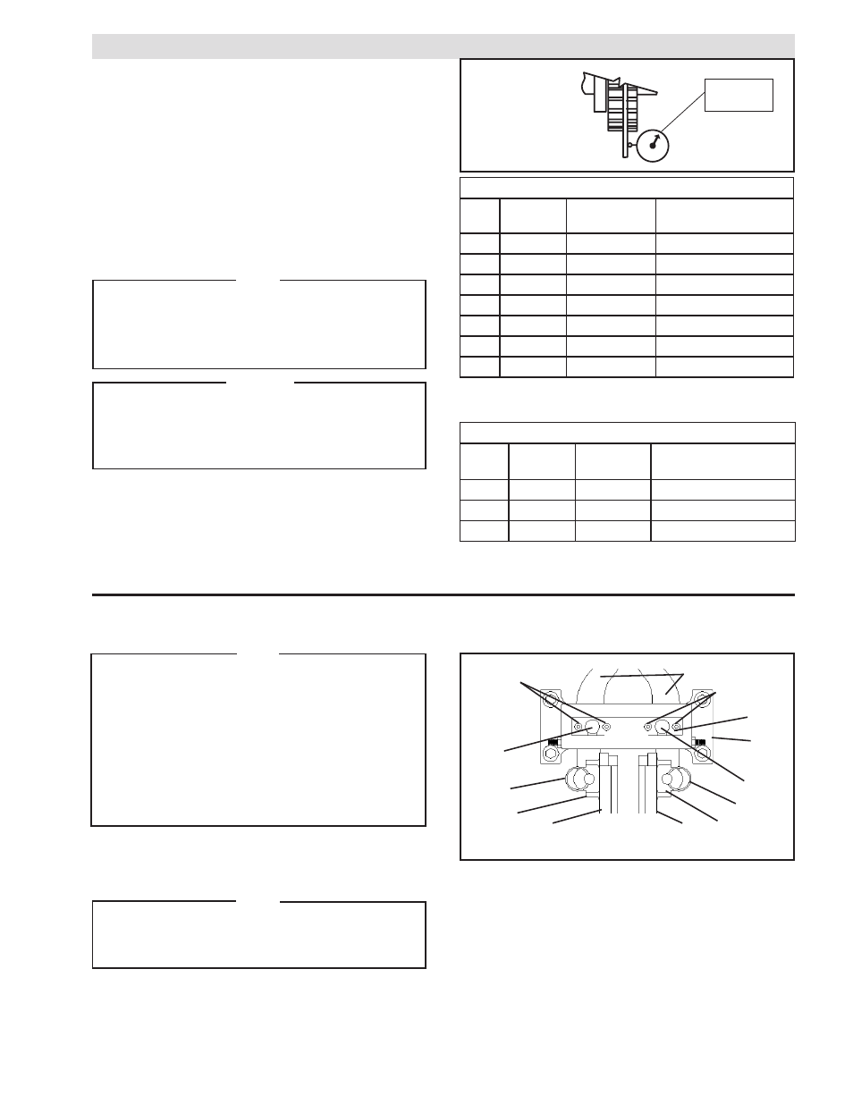
NOTE
Runout is minimized if a Dial Indicator is used as the
pull-up bolts are tightened. Place the contact tip of
the Dial Indicator on the machined surface of the rotor
to measure runout. Runout should be .010 - .015 In.
[2.5 - 3.8 mm] (See Figure 1).
CAUTION
If excessive tightening torque is applied, bursting
pressures are created in the hub. There must be a gap
between the flange of the Q.D. bushing and the disc
hub to ensure a proper press fit of the Q.D. bushing
onto the shaft.
Dial
Indicator
4. Remove Pivot Pin Retaining Plate (Item 6) (See Figure
2).
5. Press out Pivot Pins (Item 7) (See Figure 2).
6. Slide Brake Arms (Item 2) out of Main Frame (Item 1)
(See Figure 2).
7. Position the Brake Arms and Actuator as desired.
8. Slide the Brake Arms (Item 2) back into the Main Frame
(Item 1) (See Figure 2).
24
24
2
6
1
7
16
29
3
7
16
29
FIGURE 2
3
FIGURE 1
4. To remove the Q.D. bushing, remove the pull-up bolts
and reinsert into the threaded holes. Tighten the pull-up
bolts to push the disc hub off the Q.D. bushing.
TABLE 1
PULL-UP BOLT TORQUES FOR NON-VENTILATED DISCS
TABLE 2
PULL-UP BOLT TORQUES FOR VENTILATED DISCS
RECOMMENDED TIGHTENING TORQUES
DIA. PART NO.
QD
BUSHING
TORQUE
12"
934201
SF
30 ft. Lbs. [40.5 Nm]
14"
934202
E
60 ft. Lbs. [81 Nm]
16"
934203
E
60 ft. Lbs. [81 Nm]
18"
934204
J
133 ft. Lbs. [182.5 Nm]
20"
934205
J
133 ft. Lbs. [182.5 Nm]
22"
934206
J
133 ft. Lbs. [182.5 Nm]
24"
934207
J
133 ft. Lbs. [182.5 Nm]
RECOMMENDED TIGHTENING TORQUES
DIA.
PART NO.
QD
BUSHING
TORQUE
18.25"
934200
J
135 Ft. Lbs. [182.5 Nm]
21"
934300
J
135 Ft. Lbs. [182.5 Nm]
24"
934400
J
135 Ft. Lbs. [182.5 Nm]