Assembly – Ryobi RTS20 User Manual
Page 16
16
ASSEMBLY
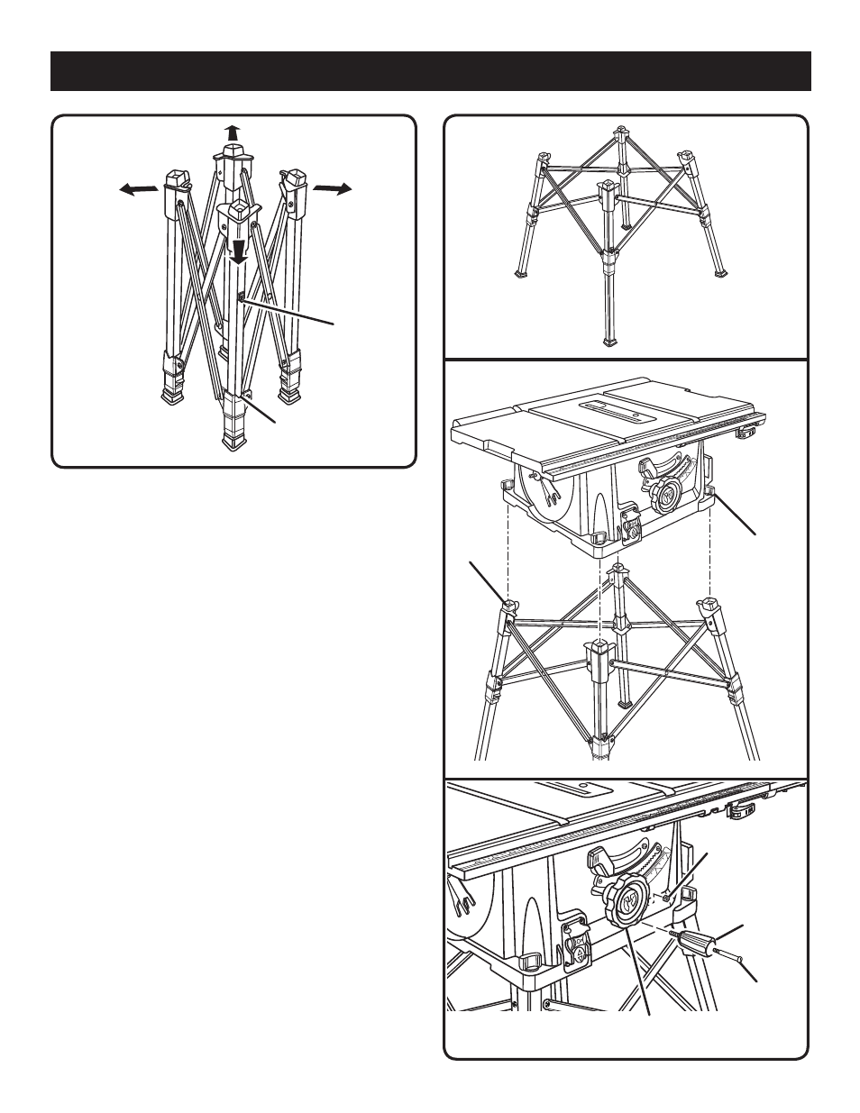
MOUNTING THE TABLE SAW BASE TO THE
QUICK STAND™
See Figure 8.
Place the table saw base on the leg stand. Position the
locking knob over the holes in the top of the leg stand.
Insert the screw on the locking knob into the hole and
turn the locking knob clockwise to secure the table saw
base to the leg stand.
Repeat with the other three locking knobs.
TO INSTALL THE HANDLE
See Figure 9.
Hold the nylon nut securely and turn the screw counter-
clockwise to remove the nut completely.
NOTE: Do not remove the screw from the handle.
Place the nylon nut into the recessed hole on the back
of the height/bevel adjusting handwheel and hold in
place.
Slide the handle and screw into the hole on the height/
bevel adjusting handwheel.
Using a flathead screwdriver, turn the screw clockwise
and tighten in place.
Fig. 8
LOCKING
KNOB
HOLE
Fig. 9
HANDLE
SCREW
NUT
HEIGHT/BEVEL
ADJUSTING HANDWHEEL
Fig. 7
Fig. 6
V SLOT
RED
INDICATOR
- BS903 (26 pages)
- BS903 (56 pages)
- ts1341 (30 pages)
- TS1350 (28 pages)
- 7-1/4 in. CIRCULAR SAW DOUBLE INSULATED CSB123 (22 pages)
- BAND SAW (24 pages)
- BTS21 (42 pages)
- BT3100 (10 pages)
- SAW BT3100 (52 pages)
- BT3100-1 (52 pages)
- JS550L (44 pages)
- JS550L (20 pages)
- MS181 (32 pages)
- CSB1308 (20 pages)
- CSB130 (2 pages)
- P550 (32 pages)
- 4730301 (10 pages)
- 7-1/4 in Compound Miter Saw TS1141 (32 pages)
- SS50 (14 pages)
- A18MS01 (12 pages)
- A18MS01 (32 pages)
- csb140lz (24 pages)
- TS230 (28 pages)
- A31TS04 (6 pages)
- CSB142LZ (6 pages)
- CSB142LZ (52 pages)
- CSB121 (22 pages)
- TS1301 (24 pages)
- TS1300 (28 pages)
- SC155VS (24 pages)
- TS1551 (30 pages)
- TS1351 (28 pages)
- TS1351 (30 pages)
- OJ1802 (18 pages)
- JSO48 (12 pages)
- SC163VS (20 pages)
- TS1550 (26 pages)
- BTS15 (38 pages)
- P530 (4 pages)
- P530 (46 pages)
- P500 (68 pages)
- P500 (24 pages)
- R10633 (20 pages)
- CSB130 (22 pages)
- JS550 (20 pages)