Assembly – Ryobi BTS16 User Manual
Page 16
16
ASSEMbLy
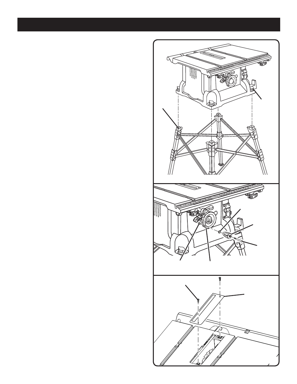
MOUNTING THE TAbLE SAw bASE TO THE
QUICK STAND™
See Figure 8.
Place the table saw base on the leg stand. Position the
locking knob over the holes in the top of the leg stand.
Insert the screw on the locking knob into the hole and
turn the locking knob clockwise to secure the table saw
base to the leg stand.
Repeat with the other three locking knobs.
MOUNTING HOLES
The table saw must be mounted to a firm supporting surface
such as a workbench or leg stand. If bolted to a workbench,
remove the four locking knobs. Four bolt holes have been
provided in the saw’s base for this purpose. Each of the
four mounting holes should be bolted securely using 3/8 in.
machine bolts, lock washers, and hex nuts (not included).
Bolts should be of sufficient length to accommodate the
saw base, lock washers, hex nuts, and the thickness of the
workbench. Tighten all four bolts securely.
Carefully check the workbench after mounting to make sure
that no movement can occur during use. If any tipping, slid-
ing, or walking is noted, secure the workbench to the floor
before operating.
TO INSTALL bEVEL HANDLE
See Figure 9.
Hold the nylon nut securely and turn the screw counter-
clockwise to remove the nut completely.
NOTE: Do not remove the screw from the handle or the
washer from the end of the screw.
Place the nylon nut into the recessed hole on the back
of the height/bevel adjusting handwheel and hold in
place.
Slide the handle, screw, and washer into the hole on the
height/bevel adjusting handwheel.
Using a flathead screwdriver, turn the screw clockwise
and tighten in place.
TO REMOVE/REPLACE THE THROAT PLATE
See Figure 10.
Lower the blade by turning the height/bevel adjusting
handwheel counterclockwise.
Loosen the screws in the throat plate.
Lift the throat plate from the saw.
To reinstall the throat plate, align the holes in the throat
plate with the holes in the saw table.
Retighten the screws, being careful not to overtighten,
which can cause the throat plate to bow or bend.
tHroat
Plate
SCreW
Fig. 8
loCKinG
KnoB
Hole
Fig. 9
BeVel
Handle
SCreW
Hex nut
HeiGHt/BeVel
adJuStinG HandWHeel
WaSHer
Fig. 10