Xaircraft autopilot instruction, Equipment installation b, Equipment installation – XAIRCRAFT Autopilot User Manual
Page 2: Awiring of autopilot, Autopilot light indication, Technology support
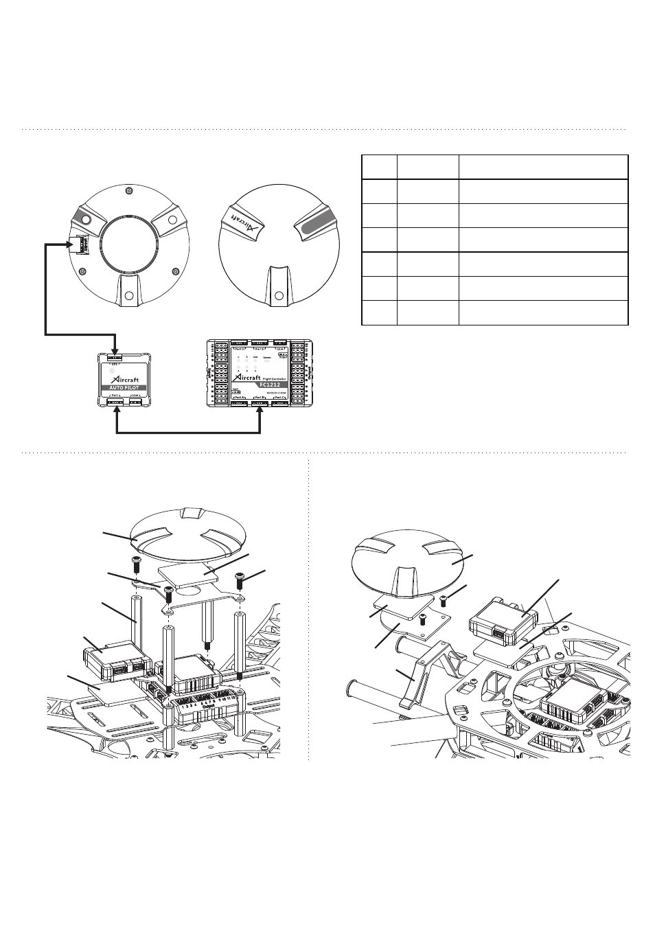
Equipment Installation B
Shock Absorber
Sponge
Autopilot
Module
GPS
GPS Mounting
Plate A
40mm Nylon Pillar
Nylon Screw
Equipment Installation
A
Wiring of Autopilot
XAircraft Autopilot Instruction
Install on X450、X450 Pro、DIY X4/X8、DIY Hexa frame etc.
Autopilot
Module
GPS
Load
Hanger
M2.5×6
Socket Screw
Install on X650 Value frame.
Red
Light
Green
Light
Red
Light
GPS Bottom View
GPS Top View
-P
6Pin Data Cable
5Pin Data Cable
GP
S
Autopilot Light Indication
Wiki: http://wiki.xaircraft.com/en-us
Email Support: [email protected]
Technology Support
XAircraft has the final power of interpretation on this manual.
1. Do not use GPS functions (Position Hold or Go home for example) between buildings.
2. GPS should leave electric system away for example Receiver etc. to avoid interference.
3. Do not work with Flight controller of FC1212-S or FC1212-S RE.
Note:
● Red Light indicates work mode of Autopilot
● Green Light indicates status of GPS
Green
Light
Light
Flash Mode
Indication
Red
Flash fast
Flight mode is Normal (NOR.) mode.
Red
One second flash
Flight mode is Attitude (ATT) Mode.
Red
Five second a flash
Flight mode is GPS Attitude Mode.
Green
Flash fast
No satellite or less than 4 satellites connected.
Green
One second flash
Low Accuracy GPS Attitude mode, 4-6 satellites
connected.
Green
Five second a flash
High Accuracy GPS Attitude mode, 7 or more
Satellites connected.
Shock Absorber
Sponge
Shock Absorber
Sponge
GPS Mounting
Plate B
Shock Absorber
Sponge