Vortech 1999-2001 Ford 6.8L Super Duty User Manual
Page 11
P/N: 8N020-100
©2002 Vortech Engineering, LLC
All Rights Reserved, Intl. Copr. Secured
28MAR02 V1.0
(99-01SDPwrCoolr(8N020-100V1.0)
5
5.
AIR INLET ASSEMBLY
A. Attach the MAF meter to the MAF bracket using
the supplied 1/4” hardware. Slide the air filter
onto the tube of the MAF bracket. Using a 5/16”
nut driver or socket, reach in through one of the
Ø5/8” holes and tighten the hose clamp. Cover
the holes with the provided finishing plugs.
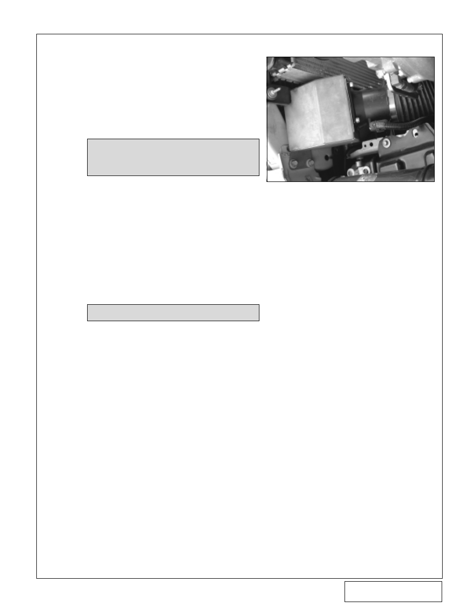
B. Install the MAF assembly onto the driver’s side
of the core support using the factory hardware.
(See
Fig. 5-a.)
C. Reconnect the MAF wiring connector to the
MAF meter.
D. Reinstall the supercharger and connect the oil
feed and drain lines.
E. Reinstall the Ø3.5” x 2” silicone sleeve and #56
hose clamps onto the supercharger inlet. Install
the cast aluminum inlet duct into the silicone
sleeve and tighten the hose clamps.
F. Connect the cast aluminum duct to the MAF
meter using the supplied Ø3.5" x 15" flex hose
and secure with #52 hose clamps.
G. Install the short end of the Ø5/8" molded elbow
hose onto the Ø5/8" bung on the air inlet.
H. Cut a 90
°
section from the stock crank case
breather hose and attach to the Ø5/8" molded
elbow hose with the Ø5/8" union. Reconnect the
other end to the crank case breather on the
valve cover. Trim hose length for a proper fit.
NOTE: The thick rubber mat may need to be
unsnapped and folded over toward the
radiator to allow proper mounting of
the MAF assembly.
?
Fig. 5-a
NOTE: Refer to Fig. A1 in the Appendix.