Vortech 1999-2001 Ford 6.8L Super Duty User Manual
Page 10
P/N: 8N020-100
©2002 Vortech Engineering, LLC
All Rights Reserved, Intl. Copr. Secured
28MAR02 V1.0
(99-01SDPwrCoolr(8N020-100V1.0)
4
4.
WATER PUMP AND COOLER INSTALLATION
A. Remove the upper shroud, located between the
core support and the grille.
B. Remove the three screws securing the radiator
reservoir and rotate out of the way.
C. Remove jack tools and tray holding brackets.
D. Remove the upper two supports securing the
condenser.
E. Remove the hood latch from the core support
(leaving it attached to the cable) and set out of
the way.
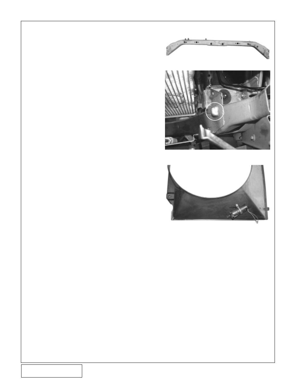
F. Remove the upper core support - secured with
(8-10) screws. (See
Fig. 4-a.)
G. Following the
Fig 7-b on page 8, install the
supplied water fitting adapters onto the heat
exchanger securing with the provided Ø3.25” x
2” sleeves and clamps.
H. Using the diagram as a guide, install the sup-
plied 3/4” NPT brass fittings into the charge
cooler as shown. A small amount of thread
sealant may be used on these threads.
I. Lower the heat exchanger into place between
the vehicle’s condenser and radiator. Rest the
heat exchanger on the pads of the lower core
support. (See
Fig. 4-b.)
J. Remove the factory nut clips if any, in the core
support and replace with the ones provided.
Secure the heat exchanger to the vehicle using
the supplied 1/4-20 x 2-3/4” cap screws and
washers.
K. Reinstall the upper core support, hood latch and
condenser supports.
L. Using the
Fig. 4-c as a guide, measure down 20”
from the top of the fan shroud and over 5” and
drill a hole through the fan shroud using a Ø9/
32” drill bit.
M. Using the supplied adel clamp and 1/4” screw,
washers and nylock nut secure the pump to the
fan shroud.
N. Cut the stock connector off of the pump wiring
and install the provided solderless connectors.
Connect the supplied red wire to the green wire
and the supplied black wire to the brown wire
using the previously installed connectors.
O. Reinstall the vehicle’s stock fan, spacer, shroud
and tighten.
P. Connect the black wire to a suitable ground, free
from paint and vehicle undercoating.
Q. Route the red wire to the vehicle’s fuse box
located near the master cylinder. Using the
supplied fuse tap, fuse holder and slide connec-
tors, tap into the #7 mini-fuse. Check that the
fuse only receives power when the key is in the
ON position using a test light.
Fig. 4-a
Fig. 4-b
Fig. 4-c