Discharge installation – Vortech 1997-2003 Ford 5.4 F-150/Expedition User Manual
Page 9
P/N: 8N020-130
© 2005 Vortech Engineering, LLC
All Rights Reserved, Intl. Copr. Secured.
19SEP05 v1.0 97-03F150PwrClr(8N020-130v1.0)
3
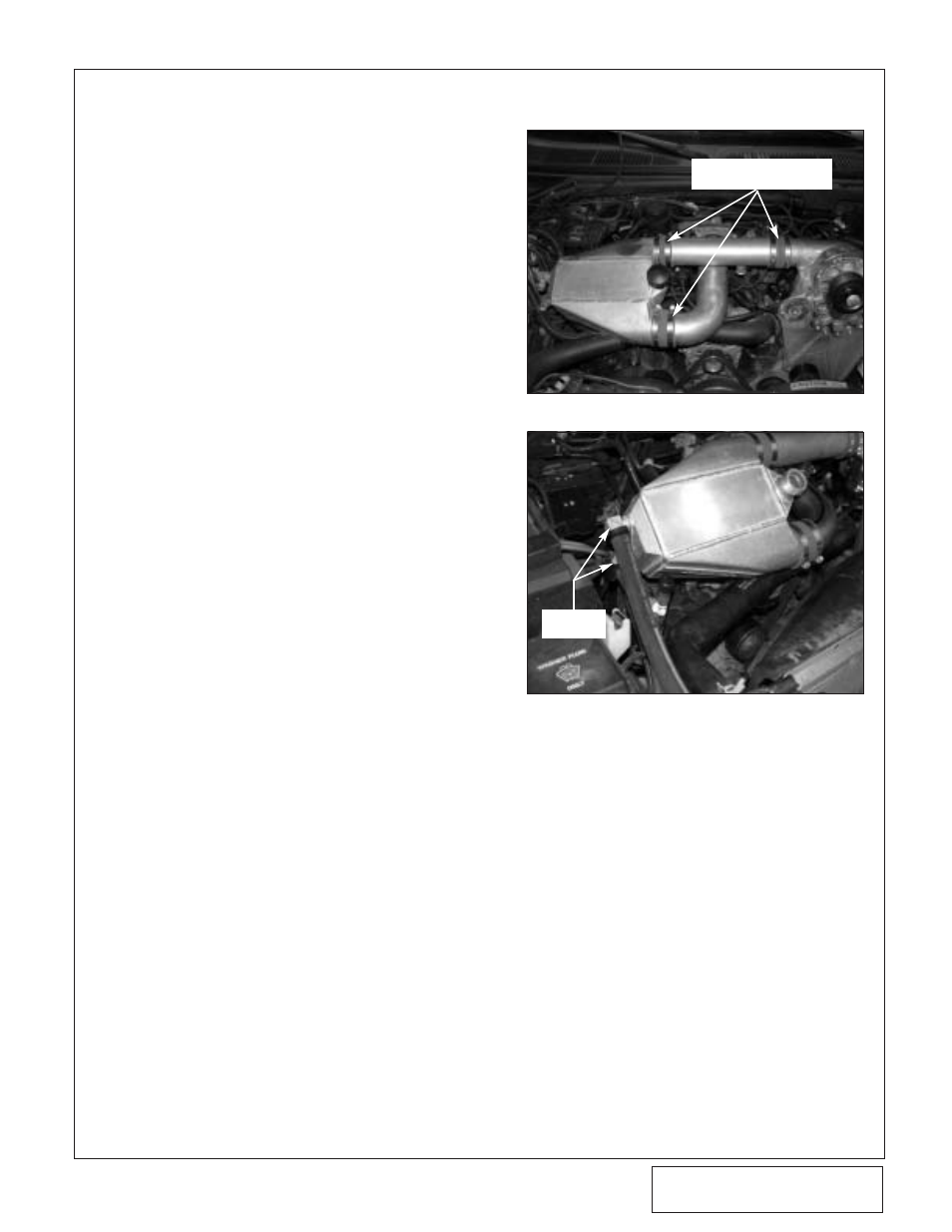
3. Discharge Installation
A.
Locate the supplied Ø2.75" straight dis-
charge duct. Using a Ø2.75" x 2.0" silicone
sleeve connect the end closest to the
bypass bung to the discharge of the super-
charger. Secure this end with #44 hose
clamps. At this time, snug the hose clamps
to leave the ability to fine tune the dis-
charge assembly. (See Fig. 3-a.)
B.
Locate the Ø2.75 x 90° discharge tube.
Using a Ø3.0" to 2.75" reducer and silicone
sleeve, connect the lightly curved end to
the throttle body. Point the 90° end of the
duct to the passenger’s side of the vehicle.
C.
Install two 3/4" x 90° brass fittings into the
two threaded ports in the supplied charge
cooler.
D.
Using the Ø2.75" x 2.0" silicone sleeves
connect the corresponding ends of the
cooler to the open ends of the discharge
ducts. Secure the Ø2.75" end with #44
hose clamps.
E.
Align the discharge assembly and tighten
all hose clamps.
F.
Lightly bend down the radiator hose sup-
port so that the charge cooler does not rub
against the radiator hose.
Fig. 3-a
Fig. 3-b
Ø2.75" SILICONE SLEEVES
& #44 HOSE CLAMPS
90° BRASS
FITTINGS