Installation, Dimensions terminal connections – TFC Group V86/1,2,3,4 Digi 322 User Manual
Page 2
2
WIRING
Make certain to connect only to the supply voltage
designated on the unit itself. Warranty will be void if
wrong voltage is applied. Connect wires to the screw
terminals in accordance with the wiring diagram
shown (use 12 to 22 AWG wire).
Install both terminal covers after wiring. Depending on
installation you may want to wire unit before snapping
to rail. For stand-alone installation use a Grasslin
indoor/outdoor enclosure, E100, E150, or E200.
INSTALLATION CHECKLIST
1. The time switch should have its own independent
circuit for power supply.
2. Since all electronic instruments are sensitive to volt-
age spikes, close attention must be paid to the fol-
lowing:
a) If possible, power to the electronic time switch
should be supplied from a phase different from
the one supplying power to the load.
b)
INDUCTIVE-LOADS
should have suitable
VARISTOR and RC network (
) across
the supply terminals to reduce voltage spikes.
c)
DC INDUCTIVE LOADS
should have a diode
across their terminals to eliminate back EMF of
the inductor.
d)
HIGHLY INDUCTIVE LOADS
, especially fluores-
cent lights, may require a relay in which case (a)
and (c) apply.
e)
IN HIGH LIGHTNING AREAS
, a surge suppres-
sor should be installed.
Installation
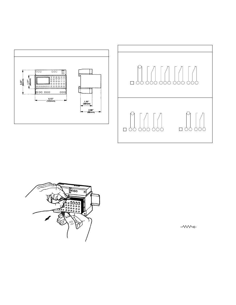
MOUNTING
Surface mounting the Digi 322 inside a control panel
or enclosure is accomplished with the supplied rail—
the rail is surface mounted with two screws. Mount at
convenient eye level position.
You are now ready to affix the unit to the rail. Place the
two protruding guides, which are on the top of the rear
rail cutout slot, over the top lip of the rail; then snap
the bottom into place.
The timer module can be removed from the timer
housing for programming or change-out purposes.
Please note that the battery needs to be charged
beforehand.
NOTE: After applying power, it may take a few minutes
for the battery to charge and display to appear.
Dimensions
Terminal Connections
Digi 322-45/4Y
*No internal connection. May be used as ground wire tie point.
*No internal connection. May be used as ground wire tie point.
Digi 322-45/2Y
Digi 322-45/1Y
4
5
6
2
3
7
8
9
10
11
12
13
14
15
NO
*
CH 1
CH 2
CH 3
CH 4
NC NO
NC NO
NC NO
NC
1
M
~
4
5
6
2
3
7
8
9
NO
*
CH 1
CH 2
NC NO
NC
1
M
~
4
5
6
2
3
NO
*
CH 1
NC
1
M
~