StorCase Technology DS50 User Manual
Page 16
DS50 User's Guide - Rev. B00
Kingston Technology Company
Installation
9
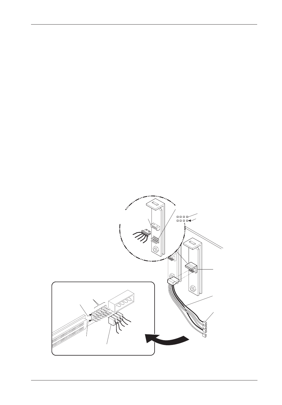
Figure 7: 16-Bit SCSI ID Cable Connection
IF INSTALLING A 16-BIT SCSI DEVICE:
The unit ID cable contains black, brown, red/black, and orange wires. Attach four
(4) connectors from the SCSI ID select cable to the appropriate 2mm drive pins
(Figure 7).
The single black wire plugs into the drive pin used to select ID0, the brown wire
plugs into the drive pin for ID1, the red/black wire plugs into the drive pin for ID2
and the orange wire plugs into the drive pin to select ID3.
In most cases, the drive manufacturer labels each pair of SCSI ID select pins in
significant bit order (0, 1 and 2). One row of drive pins is the signal row, and one
row is designated for ground. Refer to the drive manufacturer's documentation for
specific pin configurations.
The Data Silo ID select cable provides 2mm, 2-conductor drive connectors. A
single wire attaches to one side of each connector (with the exception of the red/
black connector). The cable side of each connector must align with the signal pin
on the drive. On the red/black connector, the red wire aligns with the signal pin on
the drive and the black wire aligns with the ground pin.
NOTE: Some versions of the Data Silo have a reversible ID select cable. This cable
may be attached to either 2mm or 1.25mm drive pins.
Signal Row
Black (ID0)
Brown (ID1)
Red (ID2)
Orange (ID3)
Black (GND)
GND Row
0
1
2
3
Data Silo
Back Panel
TO
Typical Drive 16-Bit Single-Ended ID Select Pins
(Pins vary on each drive model. See Drive
Manufacturer's Manual.)
Data Silo
ID Select
Connector (.1")
ID Select
Cable
ID Select Cable (2MM) from
Data Silo ID Select Connector
0537
2MM Drive
Connectors
Black (ID0)
Brown (ID1)
Red (ID2)/Black (GND)
Orange (ID3)
SCSI ID Select
Connector (1.25mm)
ID2
ID1
ID0
GND
ID3
SCSI ID Select
Connector (2mm)
ID0
ID1
ID2
ID3
Ground
Row
Pin 1