Receiving frame rear panel – StorCase Technology DE75i-SW User Manual
Page 13
6
Introduction
StorCase Technology, Inc.
DE75i-SW User's Guide - Rev. A01
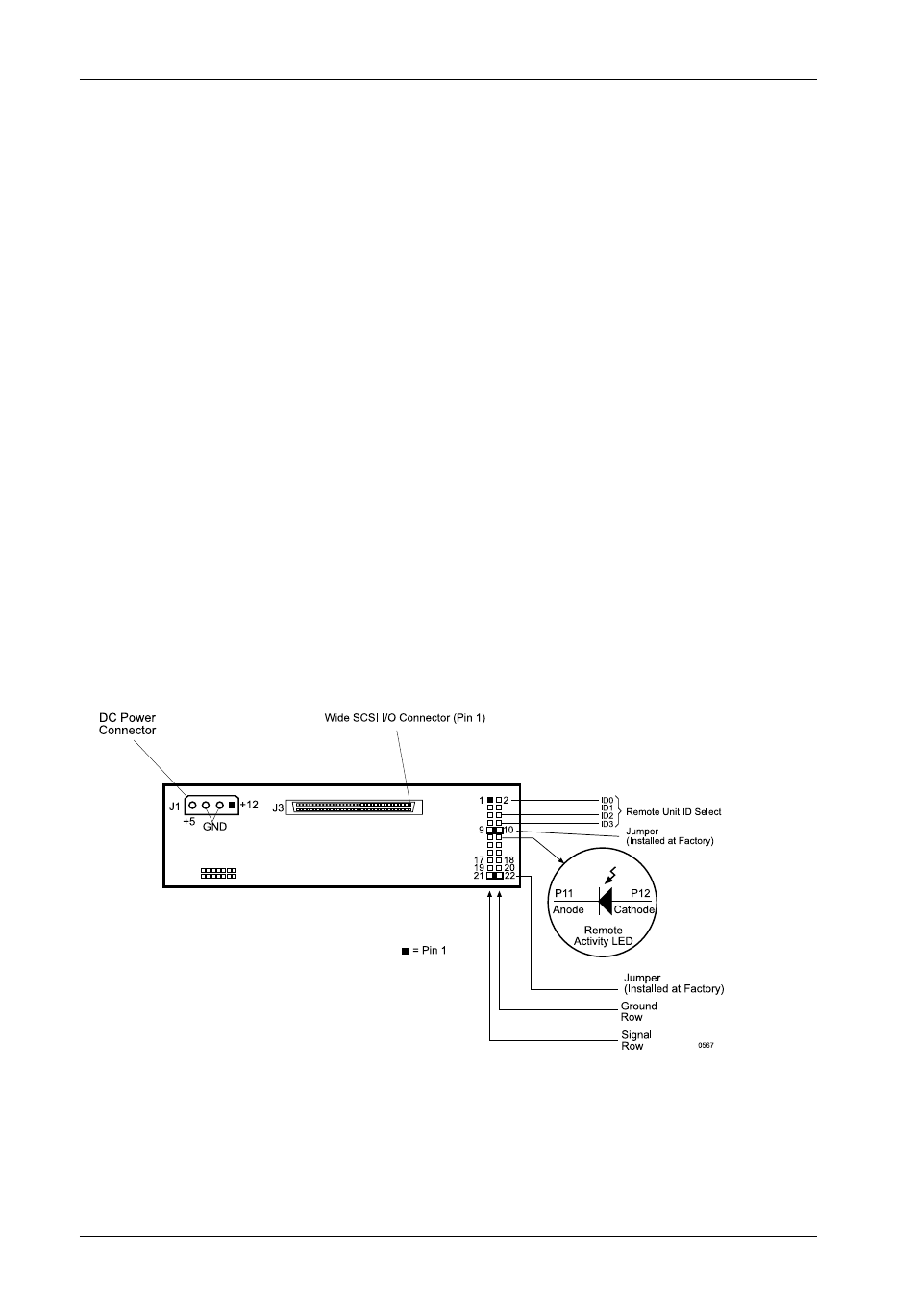
Receiving Frame Rear Panel
(Figure 5)
I/O Connector - These connectors provide a standard interface for all SCSI signals
(Figure 5). See Table 2 for pin assignments.
DC Power Connector (J1) - A standard 4-pin DC power connector is used to accept
DC power.
Option Pins
Remote Unit ID Selection - Pins 1-8 of this connector provide unit SCSI ID selection for
the computer system or expansion chassis. For remote ID selection through an expansion
chassis, an appropriate cable must be attached to these pins and the unit ID must be set
to "0". The unit ID can be set with a rotating switch located inside the receiving frame
(Figure 10).
Disable Termination (DT) - A factory-installed jumper on these pins disables termina-
tion. Removing this jumper will enable termination. Remove this jumper if the drive is
physically located at the end of a SCSI daisy chain.
Remote Activity LED (RLED) - These pins provide power for a remote LED device
activity indicator (Pin 11=Cathode, Pin 12=Anode).
Enable Termination Power To/From SCSI Bus (TPWR) - This jumper is installed at
the factory.
Figure 5: Receiving Frame Mother Board (Rear View)