Universal" receiving frame front panel – StorCase Technology SATA DE75 User Manual
Page 11
StorCase Technology, Inc.
SATA DE75 User's Guide - Rev. A00
4
Introduction
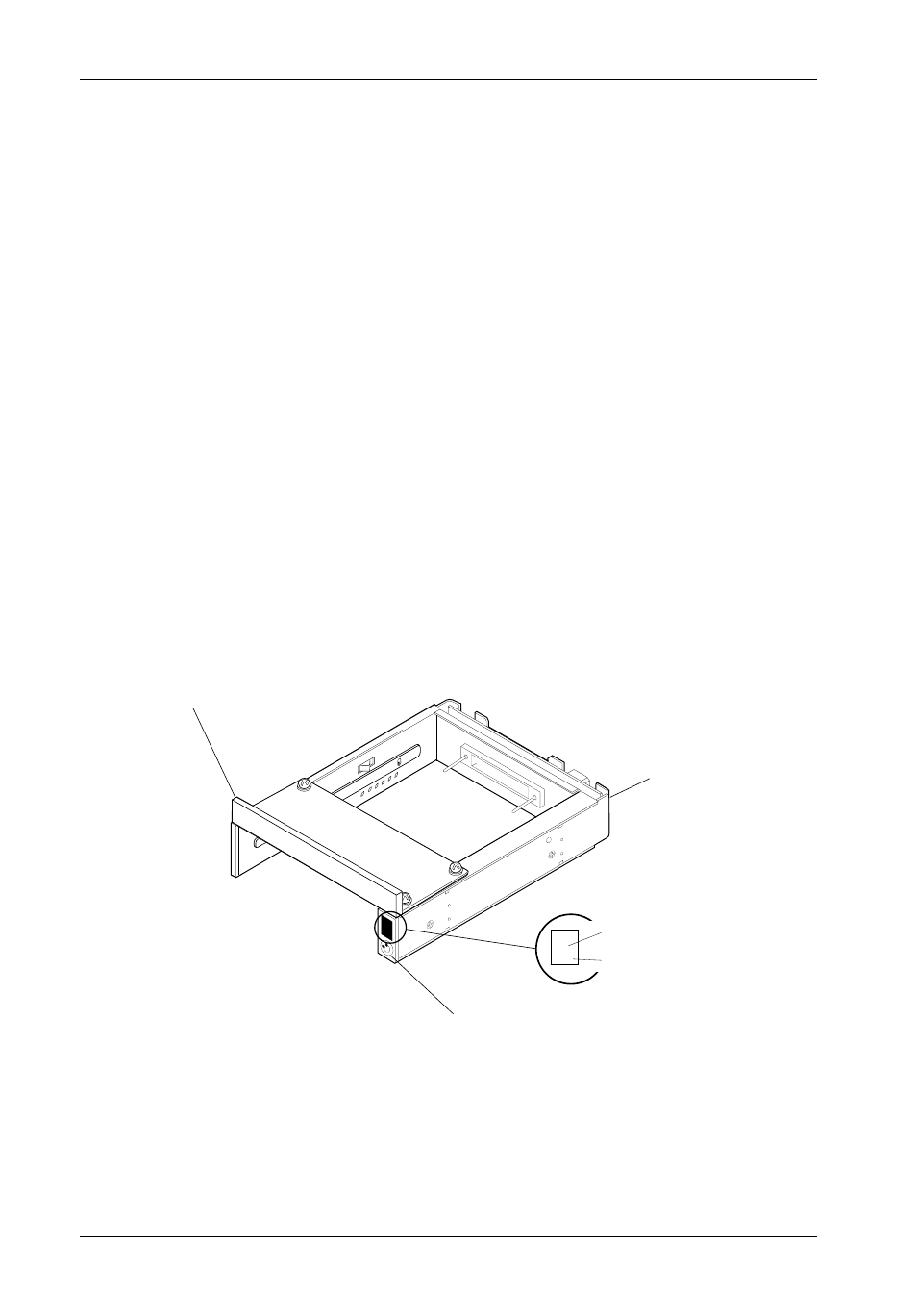
Figure 3A: "Universal" Receiving Frame Front Panel
"Universal" Receiving Frame Front Panel
(Figures 3A & 3B)
Unit ID Number Indicator - This BLUE LED displays the status of the SATA DE75 device
carrier if the carrier is Installed and Locked in the receiving frame or if the carrier is
removed from the receiving frame. If the carrier is Installed but not Locked in the
receiving frame, a "u" will be displayed to indicate an unlocked condition. The unit ID
number is selected by means of the unit ID select switch inside the receiving frame using
a special alignment tool supplied with the Serial ATA DE75 (Figure x).
The Activity Indicator - A small BLUE dot next to the unit ID number illuminates to indicate
when the host computer is accessing the data on the SATA DE75 carrier. This dot will
flash during communication with the host computer.
Some SATA host controllers provide support for the Activity Indicator feature (refer to
the SATA host controller manufacturer's documentation for further information). To utilize
the Activity Indicator, connect the Host (cable not included) to JPC1 Pin 13 located on
Receiving Frame Motherboard (Figure 4).
Refer to the SATA host controller manufacturer's documentation for further information.
Key Lock and
Power Switch
Universal
Receiving Frame
Low Profile
Filler Bracket
(Installed)
2.
BLUE Unit ID
Number Indicator
BLUE Activity
Indicator