Μin µm ra rz rv rp rt, Calibrating the gage, Measuring – Starrett SR100 Surface Roughness Tester User Manual
Page 3: Low battery indicators set up procedure, Control unit traverse unit
+
-
µin
µm
Ra
Rz
Rv
Rp
Rt
+
-
µin
µm
Ra
Rz
Rv
Rp
Rt
+
-
µin
µm
Ra
Rz
Rv
Rp
Rt
+
-
µin
µm
Ra
Rz
Rv
Rp
Rt
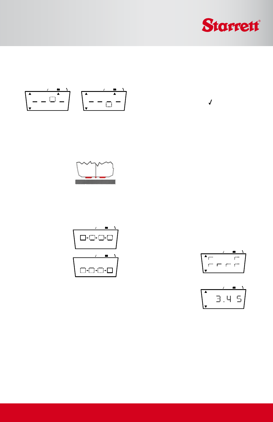
Calibrating the Gage
Position the Traverse Unit to measure the Cali-
bration Standard included with the SR100
(DO NOT use other standards). Press Mode Se-
lect (on the Control Unit) until is indicated
on Mode status.
Press the Start button on the Control Unit to ini-
tiate the gage calibration procedure. The result
will be display the Control Unit. The Ra value
should be 5.81µm and the Rz value 21.5µm.
If there is an error, an E code is displayed (see
E Codes).
Measuring
Operation of the Control Unit is identical in
either the Connected or Remote mode. Position
the Traverse Unit on the surface to be meas-
ured, then press Select on the Control Unit
to select the parameter to be displayed upon
completion of the measurement.
Select either English or metric units with the
Mode button. If in remote mode, be sure to
maintain line of sight of the infrared transceiv-
ers during the measurement.
Press either Start button
to begin the measure-
ment. The “measure-
ment in progress”
display is shown.
The measured parameter
is displayed as shown.
If there is an error, the
appropriate E code is
displayed (see E Codes).
All parameters (not just the selected param-
eter) are transmitted to the Control Unit at the
same time and temporarily stored. The stored
results may then be stepped through using the
select buttons.
Low Battery Indicators
Set Up Procedure
A new SR100 is fully set up out of the
box. However, if the pick-up is changed or
another alteration is
made, field setup may
be required using the
following procedure:
Press the On button on the Traverse Unit.
Position the traverse unit on the calibration
standard in the correct orientation. First,
press both selector buttons simultaneously
and then press the right hand start button
while still pressing both selector buttons.
The display will go
through the following
sequence over a 50
second period. The
control unit must
remain pointed at the
traverse unit during
this entire cycle.
Five values are stored and can be viewed by
toggling the Selector button as follows:
1: Gain pot setting
2: Rz value (21.5 ±10%)
3: Speed pot setting
4: Rp value (Profile period signal (68 ±2%)
5: Can be ignored for this procedure
Note: If a setup error occurs, the procedure
terminates and an E code is transmitted and
displayed in the Control Unit (see E codes).
+
-
µin
µm
Ra
Rz
Rv
Rp
Rt
+
-
µin
µm
Ra
Rz
Rv
Rp
Rt
+
-
µin
µm
Ra
Rz
Rv
Rp
Rt
Control Unit
Traverse Unit