Wiring, Power plug – Star Headlight & Lantern STAR-PA RP310Q User Manual
Page 4
-2-
Wiring
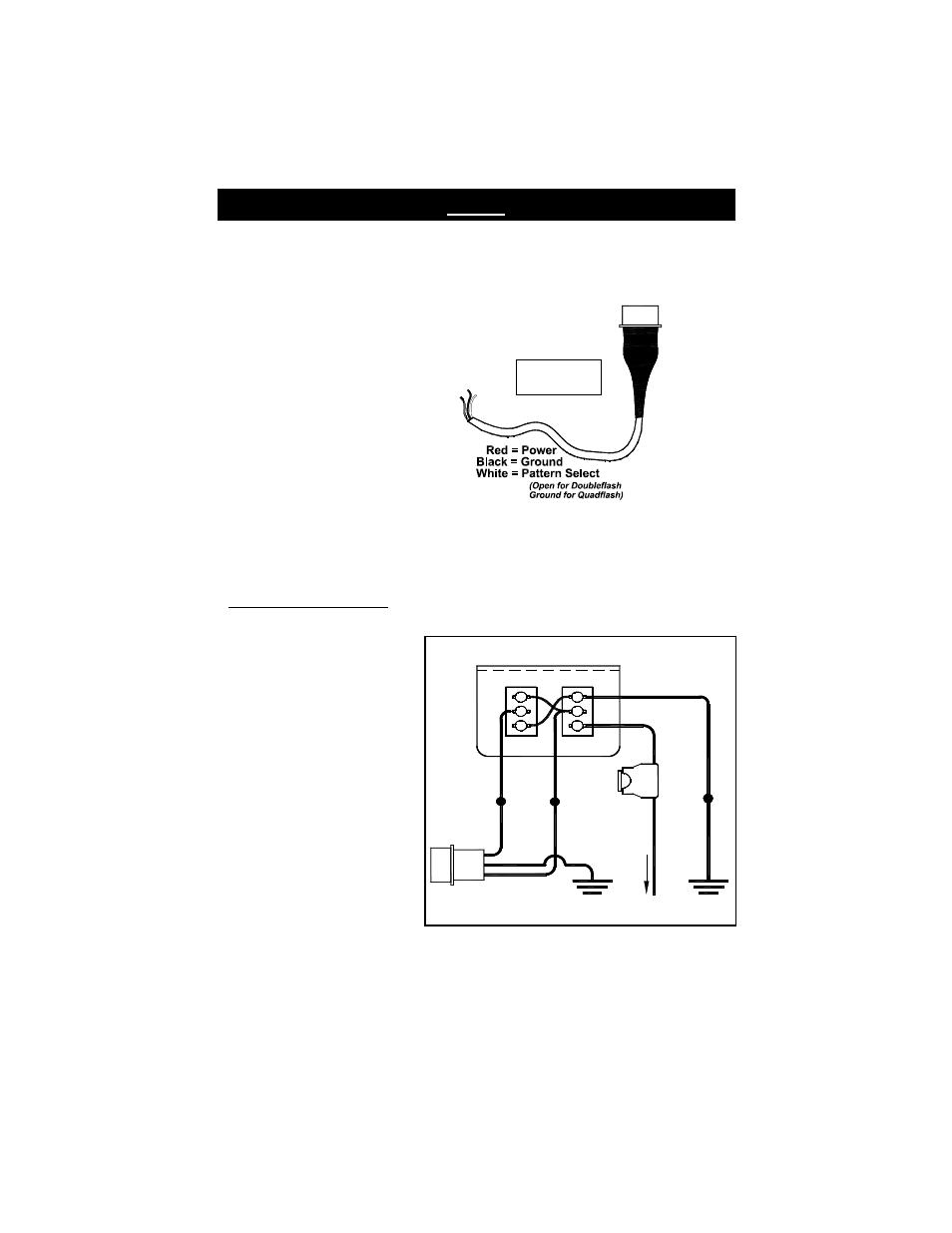
POWER PLUG
FOR RP310
PWR
CONNECTOR
Power Plug
The power plug should be included with your power pack and comes complete with an 8-12”
wiring harness. This will be connected to the outlet on your pack labeled PWR. Connect
these wires as follows:
1. The black wire should be connected
to a good chassis ground.
2. The red wire from your power plug
should be connected to +12VDC
through your on/off switch (not
included).
3. If you are only operating your power
pack with an On/Off switch, you can
select the quadflash pattern by hooking
the white wire to the black wire (good
chassis ground). If you wish display the
doubleflash pattern, cut the white wire
short and tape the end.
----------If you intend to utilize a Pattern Select Switch follow the instructions below----------
PATTERN SELECT WIRING: Make your connections as illustrated below, using the
optional #SP3860-2H switch available from your dealer.
1. The black wire from your power
plug on the pack should be
connected to a good chassis
ground, as should the black
wire from terminal 3 of SW1 on
the switch panel.
2. The red wire from your power
plug will connect to the red wire
extending from terminal 2 of
SW1.
3. The white wire from the power
plug allows for pattern selection.
It will be connected to the
purple wire from terminal 2 of
SW2 on the switch panel.
When the white wire is
connected to ground through
SW2 the pack will display a
quadflash pattern.
3
1
2
SW 1
O FF
ON
SP3860-2H SW ITC H PANEL (REAR VIEW )
w/RP310 SERIES POW ER PLUG
P
O
W
E
R
C
O
N
N
E
C
T
O
R
PLU GS
IN TO
POW ER
PAK
SW 2
2
1
3
G OO D
C HASSIS
G RO UND
B
L
A
C
K
GO OD
CHASSIS
GRO UND
C
O
N
N
E
C
T
T
O
+
1
2
V
D
C
1
0
A
M
P
F
U
S
E
R
E
D
P
U
R
P
L
E
RED
W
H
IT
E
BLACK
Q U AD
D O UB
4. The fused red lead from terminal 1 of SW1 should be connected to your
+12 VDC power supply.
5. When properly wired, SW1 will be on the left side (Front View) and switch the pack on
and off. SW2 will be located on the right side of the switch panel and will be used to
select between doubleflash or quadflash.