Ck473, Ck472, Ck703 – Star Headlight & Lantern ST415P Phanto User Manual
Page 2: Ck702
1.
The remote strobe head must be connected to a power pak to operate. You may use our
two-outlet, four-outlet, or six-outlet paks. These heads may or may not work with alternate
brand power paks. The installer accepts any and all liability if this head is used in
conjunction with any unapproved power paks.
2.
Locate the light housing you wish to install the head into. If necessary, disassemble the
light housing on the vehicle such that you can gain access to the back of the reflector.
3.
Select a location suitable to mount your strobe head. The ideal location is as close to the
focal point of the reflector as possible. The strobe head must be located at least 1” from
any other lights, the lens, and the lens housing, to allow for adequate heat dissipation.
4.
After you have checked that both sides of the mounting surface are clear, drill a 1”
hole in the reflector. Be sure to debur both sides of the hole to allow for easier insertion
and so that there is a clean, smooth surface for the strobe head to seal against.
If you have a double walled housing (i.e. an outer wall in addition to the inner reflector
wall), you will need to drill through both surfaces to properly mount your new strobe head.
Using a hole saw, drill a 1 1/4" hole in the outer wall. Once through the outer wall, the pilot
drill bit from the hole saw should start the pilot hole in the inner wall. Using the pilot hole
for centering, drill a 1" hole in the inner wall. Be sure to de-bur both sides of the hole to
allow for easier insertion and so that there is a clean, smooth surface for the strobe head
to seal against. It might be necessary to cover the 1 1/4" hole you drilled in the outer wall
to prevent contaminates getting inside the housing.
5.
To insert the strobe head, hold the rubber base with your thumb and forefinger. Slowly
twist the base while you push it into the 1” hole. Twisting while pushing helps the cup to
slide into the hole easier and helps ensure the lip on the rubber base “pops” into place
around the rubber housing.
6.
Once the strobe head is installed, reassemble the light.
7.
Attach the enclosed connector to the head by snapping the terminals on each wire into the
proper slot. Review the diagram below.
8.
Once the installation of the heads is complete, connect them to your power pak using the
proper cable:
Amp Connector
Weatherproof Connector
Light Duty Cable
3821
3820
Heavy Duty Cable
N/A
3814
Shielded Cable
4415
N/A
9.
If you intend to use your own cable, it must meet certain specifications as follows: It must
be three-conductor with 600V insulation, minimum 18 AWG for 0-20 ft., 16 AWG for 21-30
ft. or 14 AWG for 31-60 ft. We do not recommend the use of any cable length greater than
60 feet, as the resistance might cause a drop in voltage resulting in inconsistent or
complete loss of firing in the heads.
10. For good, reliable connections between the cable system and the strobe head in various
weather and contamination conditions, it is strongly recommended that a dielectric grease
be used on the connectors. It should be applied and into each terminal area where the
connectors mate, before joining the two connectors together. We also recommend
applying dielectric grease to the back of each connector where the wires enter. We have
found this procedure to be effective even under the most extreme of conditions. Do Not
Seal The Connectors Using Silicon Or RTV.
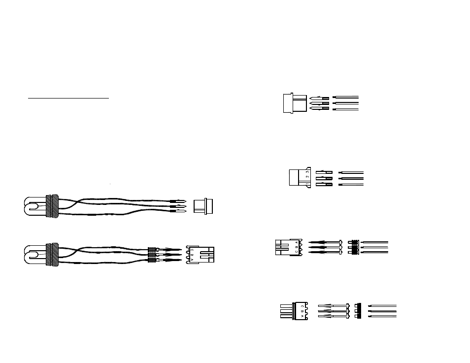
11. If you must remove the white amp connector for any reason, please re-insert the wires
back into their proper location. Please refer to the diagram below. If you need to order
another amp connector kit, please use part #CK473. This kit contains one connector (473)
and three male pins (30042-16).
12. If you need to order a white amp connector kit to mate with the CK473 (the connector on
your strobe head), please use part #CK472. This kit contains one connector (448) and
three female pins (30042-15).
13. If you must remove the weatherproof connector for any reason, please re-insert the wires
back into their proper location. Please refer to the diagram below. If you need to order
another weatherproof connector kit, please use part #CK703. This kit contains one
connector (30185-4), three male pins (30042-29), and three rubber seals (30186-2).
14. If you need to order a weatherproof connector kit to mate with the CK703 (the connector on
your strobe head), please use part #CK702. This kit contains one connector (30185-3), three
female pins (30042-30), and three rubber seals (30186-2).
30042-29
BLACK
WHITE
RED
30186-2
(TRIGGER)
(GROUND)
(HOT)
CK703
FEMALE WEATHERPROOF
CONNECTOR
30185-4
GROMMET
MALE
TERMINAL
RED (HOT)
30042-16
MALE
TERMINAL
473
FEMALE
CONNECTOR
3
2
WHITE (TRIGGER)
BLACK (GROUND)
1
CK473
30042-15
FEMALE
448
MALE
WHITE (TRIGGER)
RED (HOT)
CK472
BLACK (GROUND)
30042-30
BLACK (GROUND)
WHITE (TRIGGER)
RED (HOT)
CK702
30186-2
GROMMET
30185-3
MALE WEATHERPROOF
CONNECTOR
FEMALE
TERMINAL
3
2
1
RED (HOT)
MALE
TERMINAL
30042-16
473
BLACK (GROUND)
WHITE (TRIGGER)
FEMALE AMP
CONNECTOR
30185-4
30042-29
30186-2
RED (HOT)
WHITE (TRIGGER)
BLACK (GROUND)
FEMALE WEATHERPROOF
CONNECTOR
MALE
TERMINAL
GROMMET