Bottom view – Star Headlight & Lantern 201ZL Series User Manual
Page 3
-2-
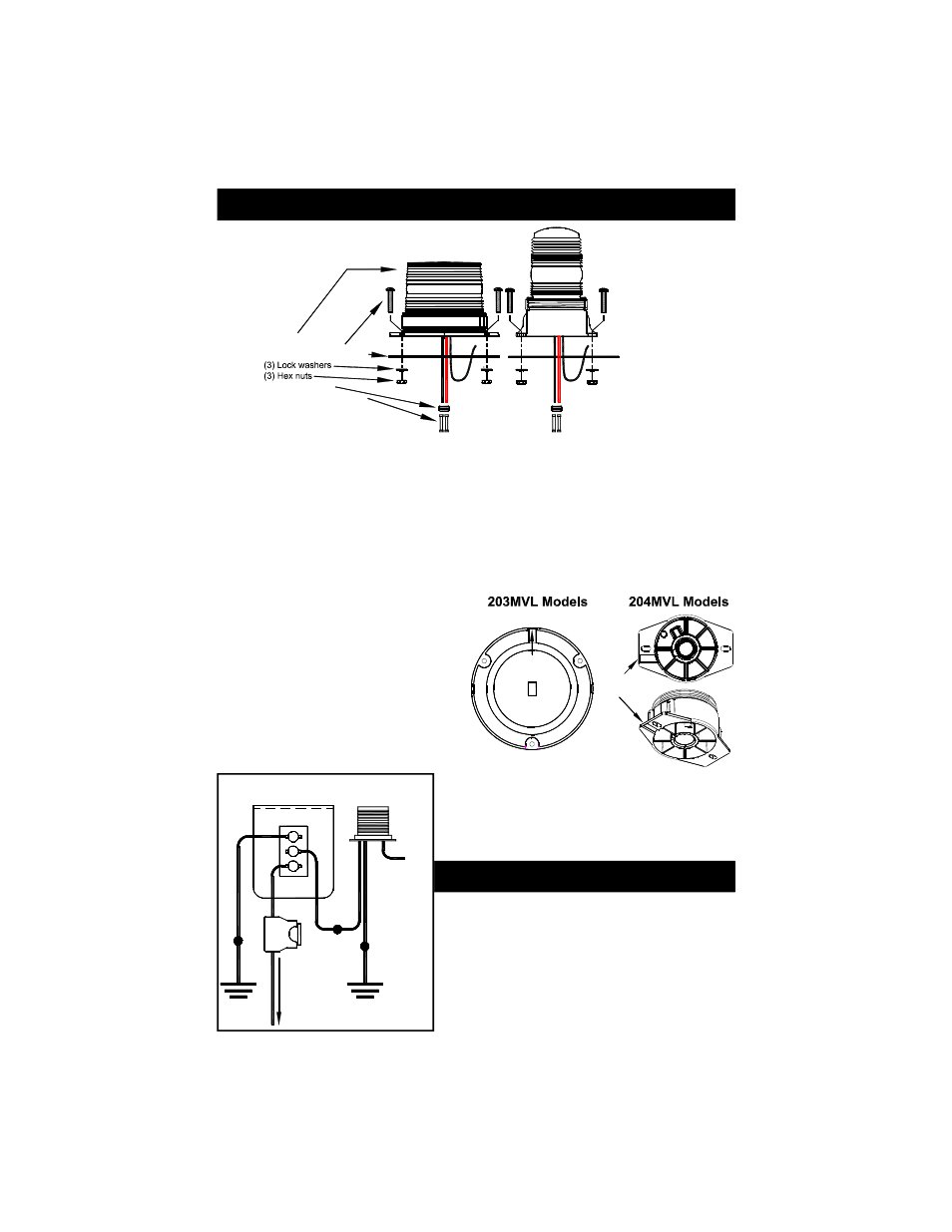
(1) Light
(3) Mounting screws
(1) Foam mounting gasket
(1) Wire grommet
(2) Wire splicing terminals
Please note that these
models only use (2) of
the following: Mounting
screws, Lock washers,
and Hex nuts
Bottom
View
Wire
Knockout
Wire
Knockout
Your new warning light comes
complete with the following:
1. Where applicable, carefully remove the headliner from the inside of the vehicle so that it
is not damaged during installation of the light.
2. Remove the foam gasket from the shipping box. Each gasket comes furnished with
mounting holes and a center wire hole. (NOTE: You might have to stretch the gasket to
find the location of the holes.) Place the gasket in the exact position the light is to be
mounted.
3. Using the gasket or base as a template, mark the mounting holes and the center hole for
the wires, if applicable, on the mounting surface. Take care to ensure that the gasket or
base does not move while you are marking each of the holes.
4. Drill a 3/16” hole in the marked spots
for the screws. If you are routing your
wires through the mounting surface,
drill a 5/16” hole in the center location
to route the wires through.
5. If applicable, insert the enclosed wire
grommet into the wire hole. If instead,
the wires will be running between the
base of the light and the mounting
surface, knock out the tab in the base
as pictured to the right.
6. Place the light on the mounting surface, routing
the wires through the grommet if necessary.
Align the outer holes of the base with the holes
in the mounting surface, install the screws and
nuts, and tighten until snug.
1. The black wire is the ground lead and should be
connected to a good chassis ground.
2. Connect the red wire to the positive side of the
power through a switch and a 5 Amp fuse,
checking the label on the warning light for
proper voltage.
3. The Green wire is used for pattern selection.
Leave disconnected and see next page.
203MVL and 204MVL Permanent Mounting
Permanent Mount Wiring
2
1
3
ON
OFF
C
O
N
N
E
C
T
T
O
+
1
2
V
D
C
GOOD
CHASSIS
GROUND
GOOD
CHASSIS
GROUND
B
L
A
C
K
5
A
MP
F
U
S
E
GOOD
CHASSIS
GROUND
GOOD
CHASSIS
GROUND
R
E
D
R
E
D
B
L
A
C
K
WARNING
LIGHT
GREEN
Cut Short After
Pattern Selected
SP3860-1 LIGHTED SWITCH PANEL
(REAR VIEW)
(12 VDC ONLY !!!)