Mounting, 110 vdc wiring, Wire knockout – Star Headlight & Lantern 204MV Series User Manual
Page 2
•
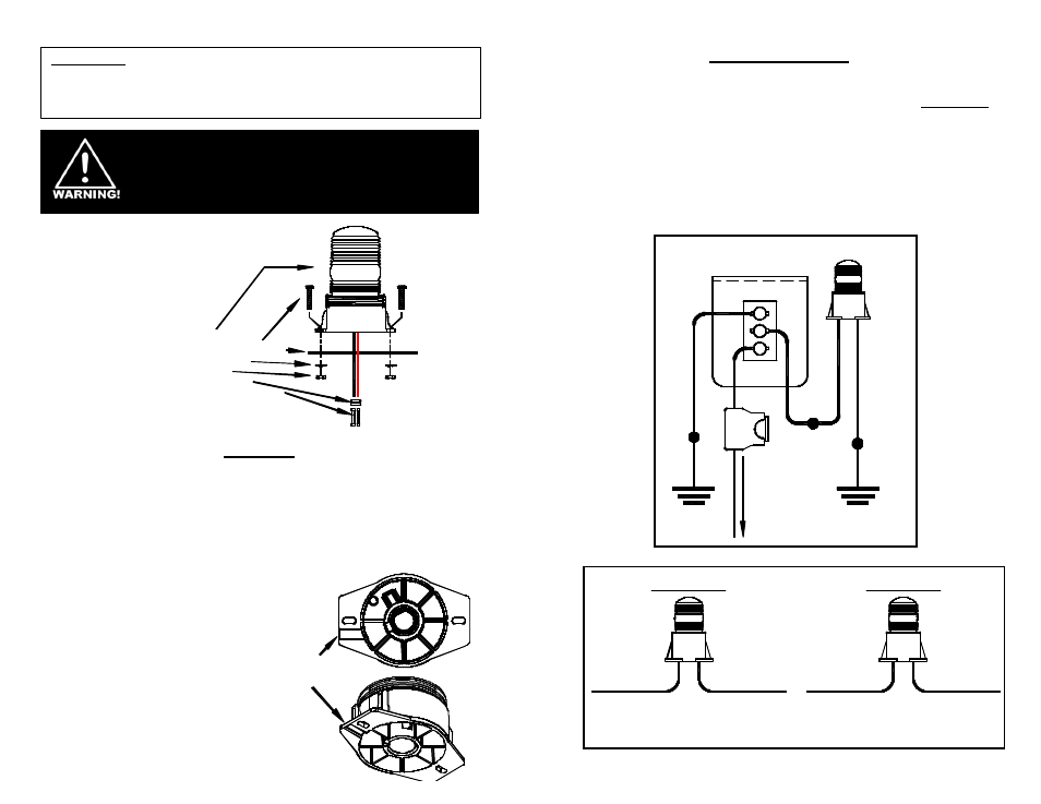
(1) Light
•
(2) Mounting screws
•
(1) Foam mounting gasket
•
(2) Lock washers
•
(2) Hex nuts
•
(1) Wire grommet
•
(2) Wire splicing terminals
Your new warning light comes
complete with the following:
Mounting
1. Where applicable, carefully remove the headliner from the inside of the vehicle so that it is
not damaged during installation of the light.
2. Remove the foam gasket from the shipping box. Each gasket comes furnished with
mounting holes and a center wire hole. (NOTE: You might have to stretch the gasket to
find the location of the holes.) Place the gasket in the exact position the light is to be
mounted.
3. Using the gasket or base as a template, mark the mounting holes and the center hole for
the wires, if applicable, on the mounting surface. Take care to ensure that the gasket or
base does not move while you are marking each of the holes.
4. Drill a 3/16” hole in the marked spots for the
screws. If you are routing your wires through
the mounting surface, drill a 5/16” hole in the
center location to route the wires through.
5. If applicable, insert the enclosed wire grommet
into the wire hole. If instead, the wires will be
running between the base of the light and the
mounting surface, knock out the tab in the base
as pictured to the right.
6. Place the light on the mounting surface, routing
the wires through the grommet if necessary.
Align the outer holes of the base with the holes
in the mounting surface, install the screws and
nuts, and tighten until snug.
10-110 VDC Wiring
1. CAUTION: All of our DC powered warning lights are polarity sensitive. Thes e
lights are polarity protected only if the appropriate fuse is used. All wires
connected to the positive terminal of the battery should be fused at the battery
for their rated load. Testing the light before this fuse is properly installed will
void the warranty on the light.
2. The black wire is the ground lead and should be connected to a good chassis
ground.
3. Connect the red wire to the positive side of your power source through a single-
pole, two position switch (not included), and a 5 Amp fuse. For 12VDC
applications you may use switch #SP3860-1 (shown below). Be sure to check
your light for proper voltage.
2
1
3
ON
OFF
CONNECT
TO +12 VDC
SP3860-1 SWITCH PANEL
(REAR VIEW)
GOOD
CHASSIS
GROUND
GOOD
CHASSIS
GROUND
BLACK
5 AMP
FUSE
GOOD
CHASSIS
GROUND
GOOD
CHASSIS
GROUND
RED
RED
BLACK
(12 VDC ONLY !!!)
WARNING
LIGHT
Please Note: These instructions are provided as a general guideline only.
Specific mounting, wiring, and/or weather-sealing may be necessary and are
the sole responsibility of the installer. Star Headlight & Lantern Co., Inc.
assumes no responsibility for the integrity of the installation for this or any
of its products.
These are HIGH INTENSITY strobes. DO NOT stare
directly into the light while it is on, as momentary blindness
and/or permanent eye damage may occur.
WARNING
LIGHT
WHITE
Connect to Neutral
BLACK
Connect to Hot
BLACK
Connect to Hot
WARNING
LIGHT
BLACK
Connect to Neutral
110 VAC
240 VAC
Wire
Knockout