Pattern programming, High/low jumper, Led indicator – Star Headlight & Lantern 400B User Manual
Page 3: The pattern select jumper is stored on pins 1 & 2
PATTERN SELECT
JUMPERS
DIAGNOSTIC
LED
S8070-159-13
RED LEAD w/FEMALE TERMINAL
(FOR RED WIRE)
MALE TERMINAL
(FOR BLACK WIRE)
3 2 1
3 2 1
MALE TERMINAL
(FOR PURPLE WIRE)
HIGH/LOW SELECT
JUMPERS
RED LEAD w/FEMALE TERMINAL
(FOR RED WIRE)
MALE TERMINAL
(FOR BLACK WIRE)
S8070-159-14
MALE TERMINAL
(FOR PURPLE WIRE)
3 2 1
PATTERN SELECT
JUMPERS
3 2 1
DIAGNOSTIC
LED
HIGH/LOW SELECT
JUMPERS
Pattern Programming
The circuits now found in these lights have a jumper on them allowing the end user to
select the desired flash pattern (singleflash, doubleflash, or quadflash). If you wish to
change the pattern, activate the light and follow the instructions below.
1. The Pattern Select Jumper is stored on pins 1 & 2.
2. To change the pattern, remove the
jumper from pins
1 & 2, momentarily place it over pins 2 & 3,
then remove it. The pattern should advance
to the next.
3. Continue to touch and release the jumper to
pins 2 & 3 to cycle through the patterns:
singleflash
à doubleflashà quadflash
4. Once you have selected a pattern,
replace the jumper on pins 1 & 2.
Please Note: Some circuits may have only two pins.
For those circuits, store the jumper on
one of the pins, and use the jumper on
the two pins for programming.
High/Low Jumper
Mag mount models will come with a
jumper that automatically defaults the light
to High Power. To only run on Low
Power, move the High/Low Select Jumper
from pins 1 & 2 to pins 2 & 3.
LED Indicator
These lights also have an LED
Diagnostic Indicator. The LED
indicator is designed to flash when the
strobe tube should be flashing. If a strobe
light is not working, troubleshooting
becomes easy with this new LED. Simply
examine the circuit when power is applied
to it. If the strobe tube is not flashing, but
the LED is flashing, you have a bad strobe
tube. If the LED is not flashing, the circuit
is either not receiving the proper voltage,
or the circuit has failed.
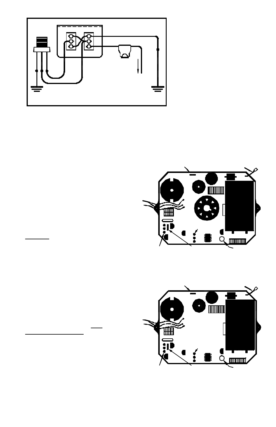
SP3860-2H SWITCH PANEL (REAR VIEW)
OFF
SW1
SW2
LOW
2
1
3
HIGH
2
1
3
ON
RED
PURPLE
BLACK
WARNING
LIGHT
PURPLE
RED
GOOD
CHASSIS
GROUND
GOOD
CHASSIS
GROUND
BLACK
10 AMP
FUSE
CONNECT RED
FUSED LEAD TO
+12 VDC
A t w o-switch switch-panel is
required to utilize the High/Low
power option. Make your
connections as illustrated above.