Cartridge loading adjustments – Simaudio 610LP Phono Preamplifier User Manual
Page 9
610LP Dual-Mono Phono Preamplifier
____________________________________________________________________________________
9
Cartridge Loading Adjustments
Prior to making any of these adjustments, always
disconnect the AC power cord and all interconnects
from MOON 610LP. We strongly recommend using
the
pen shaped
plastic hand tool
that we have
included with your 610LP as it was specifically
designed for this purpose. Using another tool made
from a material other than plastic may damage the
DIP switches and/or scratch the painted surface on
the bottom of the 610LP’. Finally, to achieve the
best possible sonic performance, it is absolutely
necessary that all settings be identical for both the
left and the right channels.
In the following examples,
the color
white always indicates the
position - left (‘ON’) or right
example to the left, the DIP switch is in the left
position (‘ON’).
This is to be consistent with the
actual white color o
(‘OFF’) of the DIP switch.
In the
f these switches.
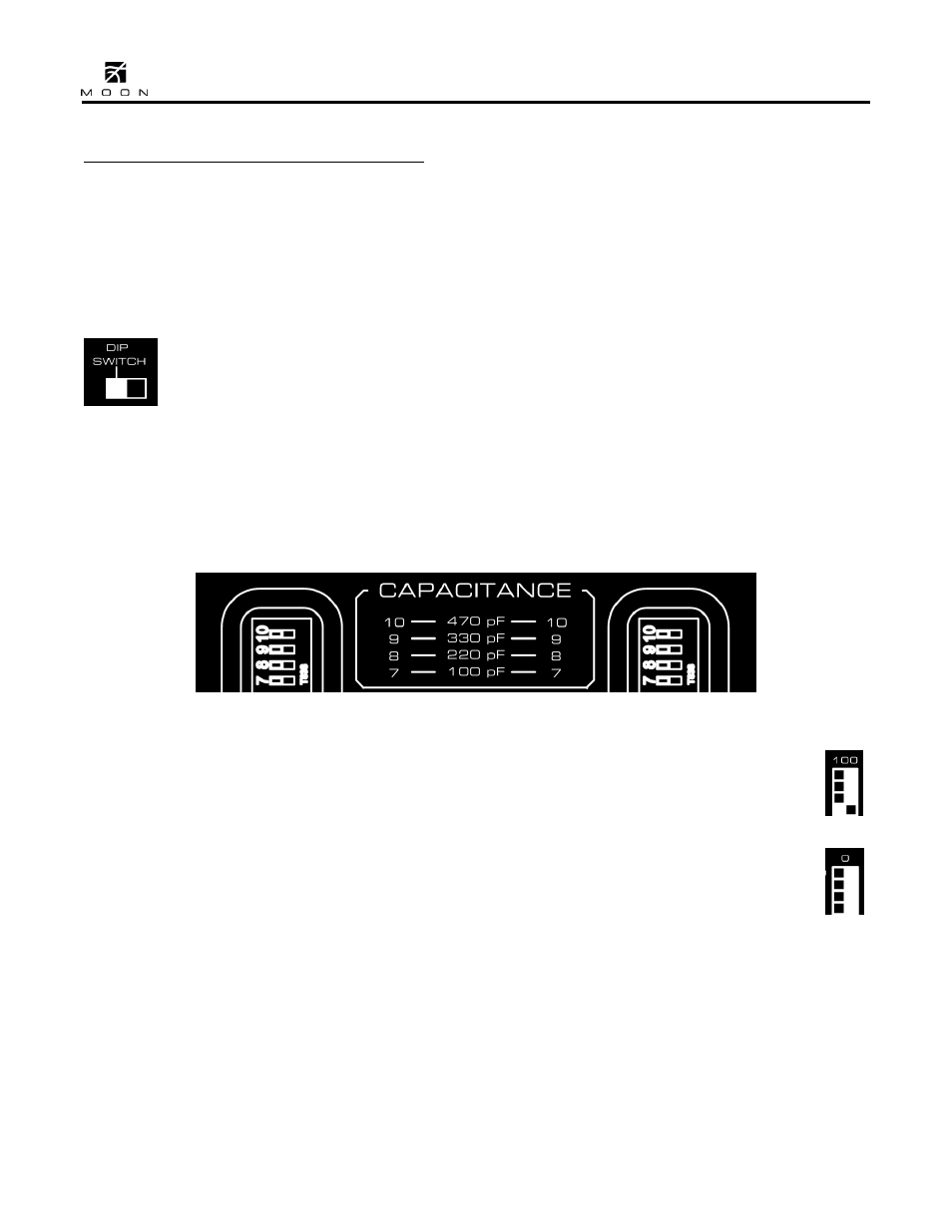
apacitance Loading:
cated at the top of the upper DIP switch bank. The
vailable settings begins at 0pF and ends at
1120pF:
C
There are sixteen (16) unique capacitance loading
settings available using DIP switches 7 through 10,
range of a
lo
Figure 2: Left and right channel DIP switches for capacitance loading adjustments
DIP switch 7 is in the left position (‘ON’) as seen in
le for most moving
magnet cartridges.
0pF. This is done by positioning all four DIP switches
(‘OFF’)
as seen in the example to the right.
represent the capacitance load if only that switch is
e left position
(‘ON’), the load value will be 220pF.
The factory default is 100 pF, whereby DIP switches
10, 9, and 8 are all in the right (‘OFF’) position and
the example to the right. This setting
would be applicab
When you are using a moving coil cartridge, you will
most likely want to set the capacitance loading to
(7, 8, 9, & 10) to the right position
A comprehensive diagram of the DIP switch
combinations for all 16 available capacitance loading
settings can be seen on the bottom panel,
immediately to the right of the switches. Finally, the
values written beside the DIP switch number
in the left position (‘ON’). For example, when only
switch 10 is in the left position (‘ON’), the load value
will be 470pF; when only switch 9 is in the left
position (‘ON’), the load value will be 330pF; and
finally when only switch 8 is in th