Rear panel connections – Simaudio 610LP Phono Preamplifier User Manual
Page 12
610LP Dual-Mono Phono Preamplifier
____________________________________________________________________________________
12
Rear Panel Connections
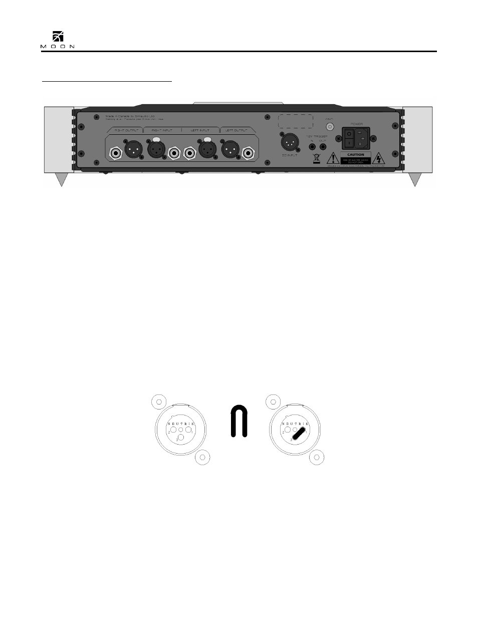
Figure 6: MOON 610LP Rear panel
The rear panel will look similar to Figure 6 (above).
All audio connectors are located on the left side of
the rear panel. As a result of the MOON 610LP
Phono Preamplifier’s balanced and symmetrical
circuit design, the layout of these audio connectors
follows the same orientation: A pair of single-ended
RCA input connectors are located in the middle and
on either side you will find the balanced XLR input
connector for that same channel. Connect the cables
from your turntable to either the RCA or XLR inputs.
The design of the 610LP allows for ONLY 1 input
connection so you cannot use both types of input
connectors
. Immediately to each side of the XLR
input connectors are the balanced XLR output
connectors. Beside each XLR output is the single-
ended RCA output connector for that same channel.
You can use either or both the XLR outputs and RCA
outputs to connect to your preamplifier/integrated
amplifier. If the preamplifier/integrated amplifier
you’re connecting the 610LP to has balanced
inputs, its highly advantageous to use the 610LP’s
XLR outputs. This will provide you with an even
better signal-to-noise ratio.
Wen you’re using the balanced XLR inputs, you
must first remove the factory installed
“dummy” XLR jumpers (see figure 7 below) from
the back panel XLR connectors and store them in a
safe place. These jumpers are required ONLY when
using the single-ended RCA inputs. In If you decide
to switch to single-ended input mode, you must
reinstall the XLR jumper (between pins 1 and 3)
exactly as show below. The purpose of these
jumpers is to help maintain the lowest possible noise
level when not using the 610LP’s balanced input
circuitry.
Figure 7: XLR connector without and with jumper accessory
To the right of the array of audio connectors is a 4-
pin XLR connector labeled “DC Input” which is
reserved for future use when an external power
supply will be made available for the MOON
610LP. Directly to the right of the 4-pin XLR are
two 12 Volt triggers, each on a 1/8” mini-jack; one
input and one output, the latter for use in if you
wish you to “daisy chain” an additional component
on the same trigger circuit. Finally on the far right
side is the “AC Power” section with a main power
switch (“0”=off, “1”=on) and IEC receptacle for the
included AC power cord.