Uv bio-wall installation manual – Sanuvox UV BIO-WALL User Manual
Page 4
5. Mounting The UV Bio-Wall
A.
Attache the four Flanges to each end of the Support Rods.
B.
After determining the ideal location within the duct, secure the first Support Rod by attaching
the Flanges to the duct wall w ith sheet metal screws.
C.
Validate the o
of the UV Bio-Wall to the air-flow (Figure 2.).
D.
Place the threaded tip of the UV Bio-Wall into the Mounting Clip (Figure 4.). Take the second
Support Rod and Flanges and place the other end of the UV Bio-Wall into the Mounting Clip.
E.
Secure the second Support Rod by mounting the Flanges to the duct wall.
7. Wiring the UV Bio-Wall to the Ballast Box
Use the included metal tie-wrap to “tie” down the wire-set to the Support Rod. Make
a small round opening in the duct to allow the wire-set to be pulled through.
Pull the colored wire-set (10 wires) from the UV Bio-Wall into the ballast box through
the round plastic connector( A.). Each pair of colored wires correspond to one of the
five UV Lamps.
Follow the wiring sequence as per Figure 5. Insert the colored wires into the terminal
block by using a small screwdriver, after which the wire will be attached to the
terminals. NOTE: Notice the individual ballasts are numbered (Figure 6.). These
numbers correspond to the numbers on the Terminal Block which facilitates locating
an individual Lamp.
Connect black to black “Line In” and white (common) to common. Each wire has a
label, as well as an orange wire connector (Figure 7.).
Maintenance
rientation
6. Mount the UV Bio-Wall Ballast Box
Install the ballast box in a convenient location. Make sure the necessary power is
available (depends on UV Bio-Wall ordered 120V / 220V / 277V).
Connect the cut-off switch on the access panel in series in the circuit so that power to the
ballast box will be cut in the event the access panel is removed.
8. Connect Power to the Ballast Box
Disconnect all power before performing any maintenance or service. Lamps
need periodic replacement to maintain design specifications. UV Lamps should
be replaced after 17,000 hours of operation. Use caution when removing and
inserting Lamps from the metal spring clamps. Only use Sanuvox replacement
Lamps for safe operation. Other Lamps may plug into the UV Bio-Wall, but they
should not be used as they were not designed to run with the UV Bio-Wall
ballast. Use only specified Lamps with this accessory. Use of an incorrect Lamp
may result in damage to accessory or Lamp.
Never look directly at the Lamp while operating. Fiberglass filter media is
recommended for operation of HVAC equipment when filters are exposed to
ultraviolet Lamps. Polyester or cotton filters are subject to ultraviolet degradation
and are not recommended.
*See Wiring Diagram for UV Bio-Wall*
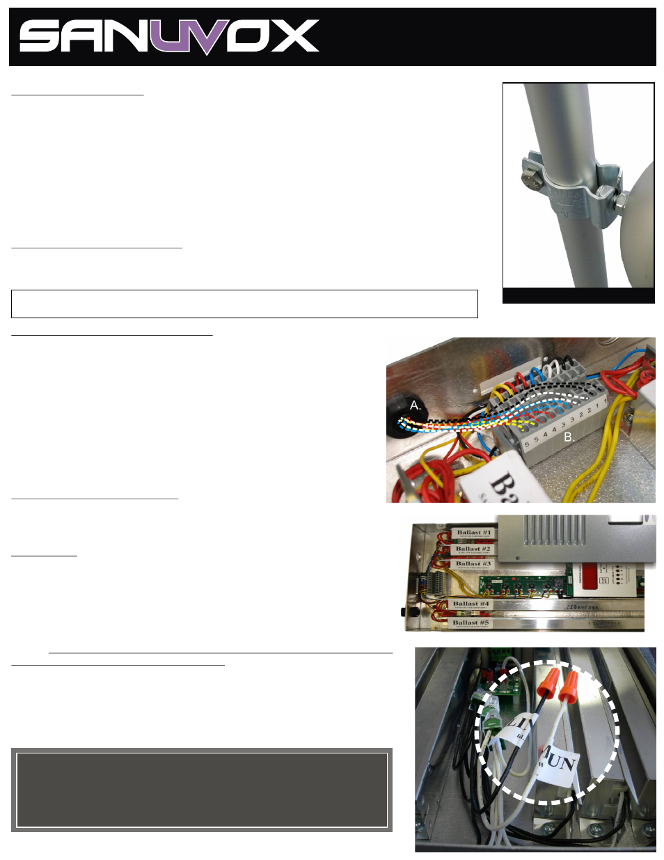
Support Rod with Flanges & Mounting Clip
Figure 4.
Figure 5.
Figure 6. with ballast cover removed
Figure 7.
Lamp Warranty: 12,000 hours.
Lamp Change-Out: 17,000 hours.
Ballast Warranty: 5 years. All other parts: 5 years
UV BIO-WALL
INSTALLATION
MANUAL