页 15, Rta-2202, P.15 – RTA Products RTA-2202 User Manual
Page 15
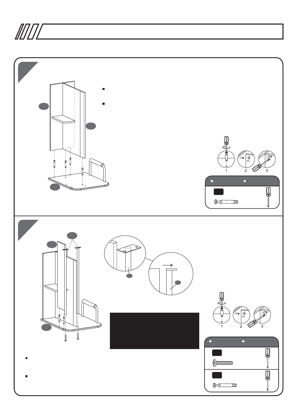
2PCS
6X40 MM
D
P.15
19
16
30
2PCS
6X30 MM
A
16
16
Side View
Front Side
Make sure to assemble
Part 16 as illustrated.
Aseg rese de ensamblar
la parte 16 como se muestra
en la ilustraci n.
ъ
у
18
19
19
20
21
4PCS
6X40 MM
D
RTA-2202
Insert Bolts (D) in the CPU Panel (19) and then place the unit
of panels 20&21 over the Bolts.
En los agujeros dispuestos para ello en el panel para CPU (19) coloque
pernos (D) y sobre ellos inserte la unidad conformada por los paneles
20-21.
Insert Bolts (D) to the CPU Panel (19), then place the CDs Wall (30)
on the bolts and secure the cam locks. Use Screws (A) to fix the
Vertical Tubes (16) to the CPU Panel (19).
SCREWS
TORNILLOS
SCREWS
TORNILLOS
Coloque los pernos (D) al Panel para CPU (19), luego coloque la Pared
de CDs (30) sobre los pernos y gire los cerrajes. Use tornillos (A) para
ensamblar los Tubos Verticales (16) al Panel para CPU (19).
- RTA-00397B (5 pages)
- RTA-1565 (11 pages)
- RTA-2018 (13 pages)
- RTA-2706 (15 pages)
- RTA-3325 (15 pages)
- RTA-3331 (9 pages)
- RTA-3343 (8 pages)
- RTA-3784 (14 pages)
- RTA-8104 (5 pages)
- RTA-8336 (8 pages)
- RTA-8338 (9 pages)
- RTA-B001N (14 pages)
- RTA-B002 (14 pages)
- RTA-B003 (4 pages)
- RTA-B005 (15 pages)
- RTA-Q203 (7 pages)
- RTA-Q207 (15 pages)
- RTA-S06 (18 pages)
- RTA-S10 (11 pages)
- RTA-B006 (11 pages)
- RTA-3309 (10 pages)
- RTA-6336 (7 pages)
- RTA-8107 (10 pages)
- RTA-220AB (12 pages)
- RTA-S06C (11 pages)
- RTA-S07 (17 pages)
- RTA-S08 (10 pages)
- RTA-S11 (9 pages)
- RTA-S13 (9 pages)
- RTA-8830 (13 pages)
- RTA-8850 (11 pages)
- RTA-8896 (10 pages)
- RTA-8897 (10 pages)
- RTA-9910 (9 pages)
- RTA-9920 (9 pages)
- RTA-1462 (14 pages)
- RTA-7732 (6 pages)
- RTA-7733 (6 pages)
- RTA-7734 (6 pages)
- RTA-7735 (6 pages)
- RTA-8807 (15 pages)
- RTA-8811 (13 pages)
- RTA-4804L (29 pages)
- RTA-4805L (30 pages)