Parr Instrument CAL 9500P User Manual
Page 3
w w w . p a r r i n s t . c o m
3
Instructions
Cal 9500P
Installation Instructions
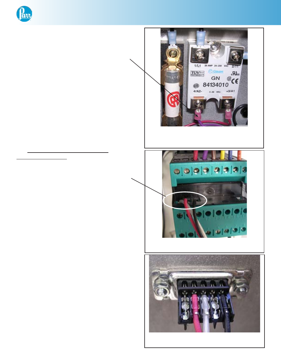
18. Trace this purple (or blue) wire to terminal
block location 7 and remove from the terminal
block. Attach this wire to position 20 of the Cal
9500P. (See Figure 6)
19. Optional step to connect RS-232
communication wire: (See Figure 7)
Connect the white/clear wire of the A1845E
communication harness to position 9 of the
Cal 9500P.
Connect the red wire of the A1845E to
position 10.
Connect the black wire of the A1845E to
position 11.
Mount the 9-pin connector to the rear panel
of the 4840 with the hardware provided. (See
Figure 8)
20. Close the hinged front cover and reinstall
the two retaining screws (removed in step 1).
21. Reconnect power cord to the 4840
Controller.
(#1119E) Solid state relay for use with
Cal 9500P (to be installed)
Figure 6
Back of Cal 9500P with wiring
Figure 7
Back of RS-232 with wiring
Figure 8