Parr Instrument CAL 9500P User Manual
Page 2
Cal 9500P
Installation Instructions
2
P a r r I n s t r u m e n t C o m p a n y
10. Connect the wires of the Cal 9500P
temperature controller as follows: (See Figure 4)
Wire:
Cal Pin #
Position:
Function
Black
7
Power
White
8
Power
Orange
24
High limit
Blue
23
High limit
Brown
21
SVM
Yellow
22
SVM
Red
19
SSR
Purple
20
SSR
T/C White
(Type J)
1
T/C
T/C Red
(Type J)
2
T/C
11. Remove the four wires connected to the
solid state relay on the back panel of the 4840
controller. (See Figure 5)
12. Remove the solid state relay from the back
of the 4840 controller and resistor if present.
Discard the old solid-state relay and resistor.
1
3. Install the provided solid-state relay (part #:
1119E) on the back panel of the 4840 controller.
(See Figure 6)
14. Attach the short black wire to position 1 of
the relay.
15. Attach the long black wire to position 2 of the
relay.
16. Attach the red wire to position 3 of the relay.
17. Attach the purple (or blue) wire to position 4
of the relay.
Back of Cal 9500P with wiring
Figure 4
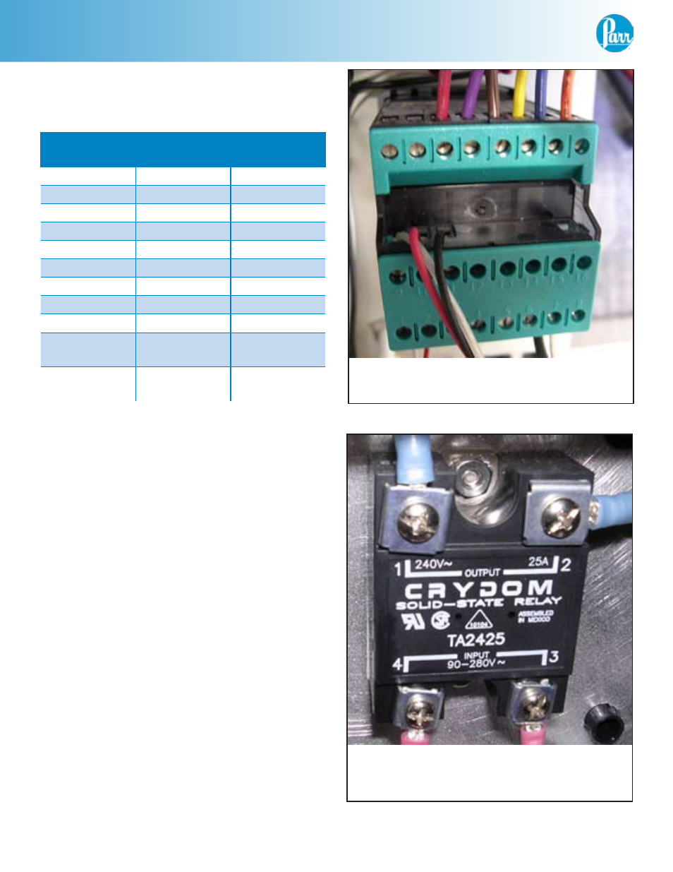
Solid state relay for use with Watlow
(to be replaced)
Figure 5