Html installation – Parr Instrument ETLM-HTML User Manual
Page 5
HTML Installation
w w w . p a r r i n s t . c o m
5
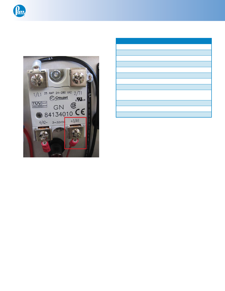
Locate the free yellow wire #5 from the kit and
8.
attach one end to pin 10 on the 2082E meter. The
other end attaches to the 1119E solid state relay
(position 3).
SSR Position 3
Pin Outs:
2082E
Color:
Attaches to:
Pin 1
Black
Terminal Block 5
Pin 2
White
Terminal Block 2
Pin 3
Pin 4
White
T/C jack +
Pin 5
Pin 6
Red
T/C jack -
Pin 7
Blue
Terminal Block 7
Pin 8
Orange
Terminal Block 6
Pin 9
Red
2083E Primary Temp
Meter
Pin 10
Yellow
1119E SSR (3)
Pin 11
White
Terminal Block 4
Pin 12
Black
Terminal Block 3
* White (Type – J), Yellow (Type – K), Blue (Type – T),
Black (RTD)
** Red (Type – J, Type – K, Type – T), White (RTD)
Final Steps:
Close the controller and replace the two screws on
the top plate. Plug the 4848 controller back in, and
turn it on.
It is useful to check that the settings on the display
are set correctly. Check these against the defaults
listed in the back of these instructions.