Html installation – Parr Instrument ETLM-HTML User Manual
Page 4
HTML Installation
P a r r I n s t r u m e n t C o m p a n y
4
Wiring Installation in 4848 Reactor
Controller (Continued)
Warning: Take care not to apply too much torque when
tightening down on wires. This can cause them to
weaken and break.
Take the black and white cable, with both ends
1.
stripped, from the kit and attach one end to the
2082E meter. Connect the white wire #6 to pin
11 and black wire #7 to pin 12.
Attach the other stripped end of white wire #6 to
terminal block position #4 and the black wire #7
to terminal block position #3.
Note: The terminal block position can be opened up
using a small fl at head screw driver to release the
tension from the spring inside the block so you can
press the wire against the spring.
Wago Terminal Block
Find the free black wire #4 from the kit and at-
2.
tach one end to pin 1 on the 2082E meter. The
other end attaches to terminal block position #5.
Find the free white wire #3 from the kit and at-
3.
tach one end to pin 2 on the 2082E meter. The
other end attaches to terminal block position #2.
Find the free orange wire #1 from the kit and
4.
attach one end to pin 8 on the 2082E meter. The
other end attaches to terminal block position #6.
Find the free blue wire #2 from the kit and attach
5.
one end to pin 7 on the 2082E meter. The other
end attaches to terminal block position #7.
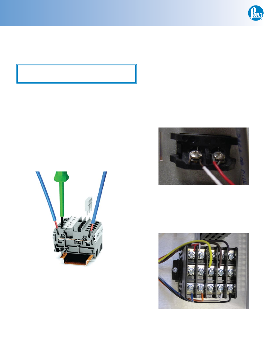
Locate the thermocouple jack on the back of the
6.
4848 Controller labeled “TEMPERATURE INPUT”.
Slip one 1541E bead on the red and the white
wire. Attach the 1398E2 internal thermocouple
wire to the jack by wrapping the wires around
the posts and tightening them.
T/C Jack
Locate the 2083E Primary Temperature Meter.
7.
There is a red wire connected between pin 2 and
the 1119E solid state relay (position 3). Remove
the tabbed end of this wire from the 1119E and
attach it to the 2082E ETLM meter on pin 9.
Back of 2083E
Primary Temperature Meter