Htm installation, Wiring installation in 4848 reactor controller – Parr Instrument HTM User Manual
Page 3
HTM Installation
w w w . p a r r i n s t . c o m
3
Wiring Installation in 4848 Reactor
Controller
Warning: Take care not to apply too much torque when
tightening down on wires. This can cause them to
weaken and break.
1. Take the black and white cable, with both ends
stripped, from the kit and attach one end to the
2082E meter. Connect the white wire #6 to pin
11 and black wire #7 to pin 12.
Attach the other stripped end of white wire #6 to
terminal block position #4 and the black wire #7
to terminal block position #3.
Note: The terminal block position can be opened up
using a small fl at head screw driver to release the
tension from the spring inside the block so you can
press the wire against the spring.
Wago Terminal Block
2. Find the free black wire #4 from the kit and at-
tach one end to pin 1 on the 2082E meter. The
other end attaches to terminal block position #5.
3. Find the free white wire #3 from the kit and at-
tach one end to pin 2 on the 2082E meter. The
other end attaches to terminal block position #2.
4. Find the free orange wire #1 from the kit and
attach one end to pin 8 on the 2082E meter. The
other end attaches to terminal block position #6.
5. Find the free blue wire #2 from the kit and attach
one end to pin 7 on the 2082E meter. The other
end attaches to terminal block position #7.
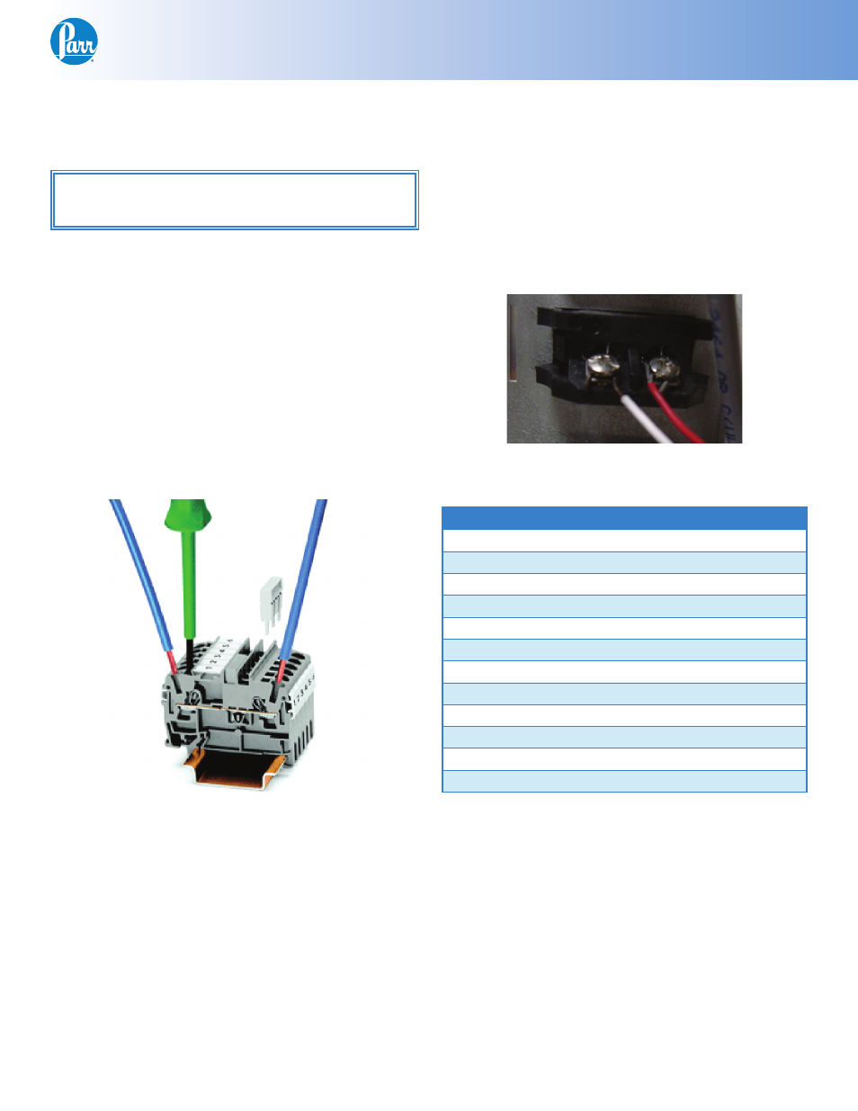
6. Locate the thermocouple jack on the back of the
4848 Controller labeled “TEMPERATURE INPUT”.
Slip one 1541E bead on the red and the white
wire. Attach the 1398E2 internal thermocouple
wire to the jack by wrapping the wires around
the posts and tightening them.
T/C Jack
Pin Outs:
2082E
Color:
Attaches to:
Pin 1
Black
Terminal Block 5
Pin 2
White
Terminal Block 2
Pin 3
Red (RTD)
RTD jack (RTD Only)
Pin 4
White*
T/C jack +
Pin 5
Pin 6
Red **
T/C jack -
Pin 7
Blue
Terminal Block 7
Pin 8
Orange
Terminal Block 6
Pin 9
Pin 10
Pin 11
White
Terminal Block 4
Pin 12
Black
Terminal Block 3
* White (Type – J), Yellow (Type – K), Blue (Type – T),
Black (RTD)
** Red (Type – J, Type – K, Type – T), White (RTD)
Final Steps:
Close the controller and replace the two screws on
the top plate. Plug the 4848 controller back in, and
turn it on.
It is useful to check that the settings on the display
are set correctly. Check these against the defaults
listed in the back of these instructions.