Bottom drain valve model a177vb2 – Parr Instrument A177VB2 User Manual
Page 2
Bottom Drain Valve Model A177VB2
P a r r I n s t r u m e n t C o m p a n y
2
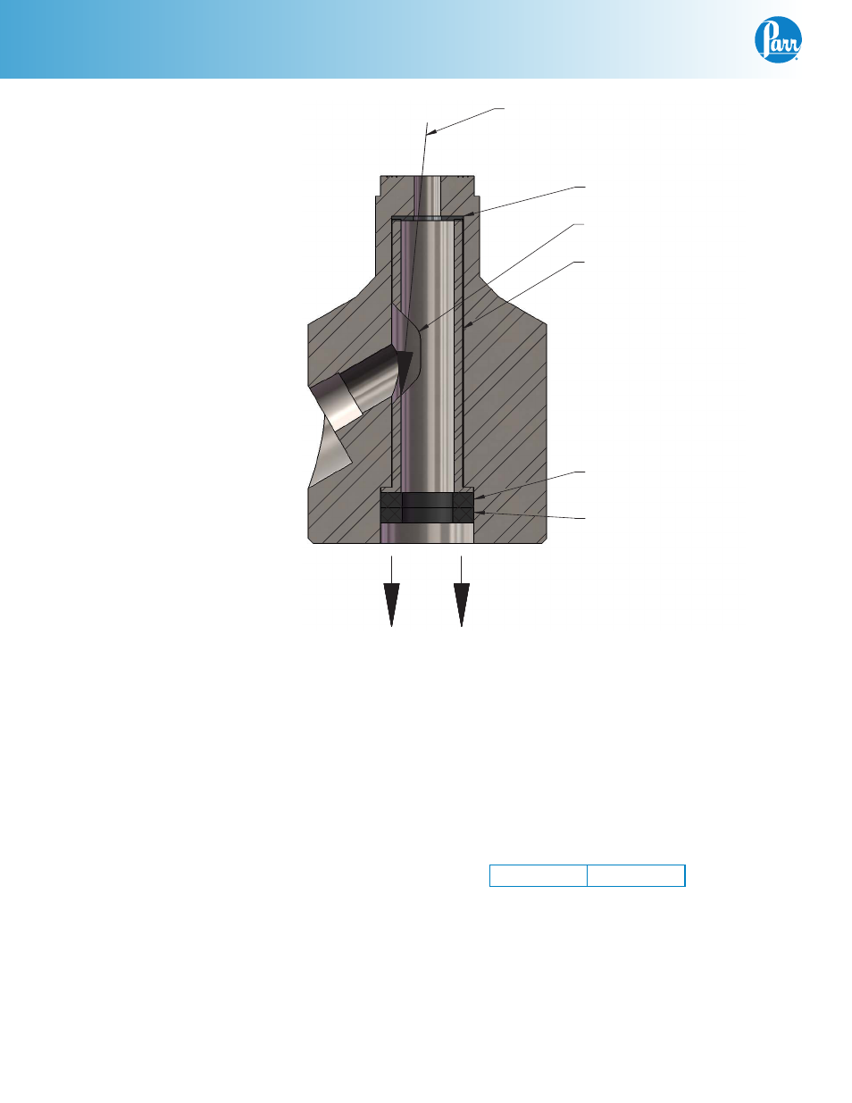
Figure A-A
Assembly of Bottom Drain Valve
1. Before assembly, all parts of the valve should be
clean and in good condition.
Note:
Assembly of the valve is easier if it is removed
from service and oriented so that the threads going
into the cylinder face downwards.
2. Apply generous amounts of lubrication using
a high temperature thread lubricant. See the
“Lubrication of the Bottom Drain Valve” section
in this manual.
3. Install a 511VB5FH silver or 511VB5FG gold faced
(depending on BDV material) seal 1 into the cav-
ity in the valve body. The plunger may be used
to help with the installation.
4. Install the sleeve, and orientate it so the opening
is positioned over the valve drain opening.
5. Install the Graphoil seal 2 (front) and next the
PTFE seal 2 (back).
6. Install the retainer and start the (3) 5/16 socket
head cap screws.
7. Install the plunger assembly.
8. Tighten the retainer into valve body to the fol-
lowing torque:
A177VB2
100 in/lbs
9. Install the (3) standoffs.
10. Install the (3) 5/16 flat countersunk socket head
screws with the plunger retracted away from
seal 1.
11. Turn the shaft screw clockwise until the plunger
contacts seal 1.
BACK SEAL (PTFE)
FRONT SEAL (GRAPHOIL)
SEAL 1
SLEEVE OPENING
SLEEVE
DISASSEMBLY STEP 7