M type connectors and signals, 4. connectors and signals – Parr Instrument DP8340R Series User Manual
Page 30
– 26 –
7-4.
Connectors and Signals
Pin No.
Signal
Direction
Function
Name
1
GND
—
Shield Ground
2
GND
—
Frame Ground
3
TXD
OUT
This pin carries data from the printer.
(Return channel)
4
RXD
IN
This pin carries data to the printer.
5
RTS
OUT
This is SPACE when the printer power is ON.
6
FAULT
OUT
This is MARK when the printer is abnormal.
(Refer to Error Condition Alarm Mode *1.)
Or there is a paper error.
7
GND
—
Signal ground.
8
DTR
OUT
This printer turns this pin SPACE when
it is ready to receive data.
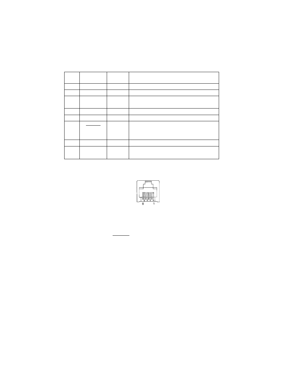
Figure 7-3. Modular Jack Connector
*1 Error Condition Alarm Mode
If an error condition is detected during operation, the printer will stop
printing and cause the FAULT signal to go MARK. All solenoides &
motors will be de-energized. It is necessary to turn the printer power
off and on again in order to recover from the alarm mode.
This printer can detect the following error coditions:
a. Motor Lock
b. Defective timing detector
c. Micro-proccessor out of program sequence