ParkZone PKZ4980 User Manual
Page 8
13
14
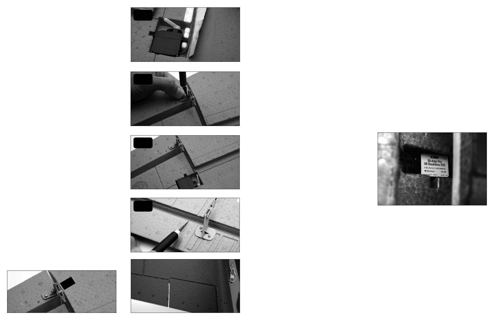
Optional Flaps
The Bf-109G is equipped with servo pockets in the wing
for making the flaps operational. To make the flaps
functional you will need two additional servos (PKZ1081),
the flap pushrod set (PKZ4921), and a Y-harness
(PKZ1063).
1. Plug Y-harness into the flap or gear channel of the
receiver. Plug flap servos into the y harness. Power
on radio and move the flap switch to the up position.
Turn off radio and unplug airplane. (see image 2 for
servo arm orientation in the up position).
2. Place servos in flap pockets using hot glue, silicon
glue, or double-sided servo tape. Peel back the tape
covering the servo lead and run the flap servo leads
in the same channel. Re-secure the tape over the
servo leads.
3. With the ailerons in the neutral position attach
control horn so the holes in the horn are over the
hinge line. Use the aileron control horns for position
reference.
4. Attach pushrod to servo control horn and adjust
clevis so it attaches to the control horn on the outer
hole without pushing or pulling on the aileron.
5. Cut the aileron at the panel line on the aileron. Make
sure there is 1/16 inch gap between the aileron
and flap to prevent interference between the two
surfaces.
6. Power on the airplane and radio and make sure you
are getting even throw on both flaps.
Note: When the flaps are installed the aileron area is
much smaller than whenusing the full span ailerons.
The roll rate in flight will be reduced. The aileron throw
can be increased to compensate for the reduced
aileron area. See step 9 for control throw for the
ailerons with flaps installed.
Note: The flap servo pockets have been positioned so
it is possible to make the inboard flaps operational. This
will require the purchase of an additional flap linkage
set. The outline for the inner flap is on the top surface
of the wing. Hinging options are up to the modeler to
implement. Picture below shows placement of additional
control horn for inboard flaps.
Note: The recommended settings are set at the default
settings (see point #5, page 11).
30-Amp Pro Switch-Mode BEC Brushless
Controller
Your Bf-109G BNF comes out of the box with the E-flite
30-Amp Pro Switch-Mode BEC Brushless Controller. This
controller has been designed for use in radio control
aircraft and is designed to support motor currents up
to 30 amps continuous, and a 5-volt Switch-Mode BEC
circuit capable of 700mAh continuous current on any
recommended input voltage with a 3- to 4-cell Li-Po
battery. It is suitable to use with most radio brands.
If you intend to fly your Bf-109G BNF stock, then there
is no need to program your ESC. It comes installed with
the default settings. If you intend to re-program the ESC,
we strongly recommend removing the propeller first in
order to keep it from spinning if the motor is accidentally
engaged.
Note: ALWAYS assume the motor and the propeller
are live. ALWAYS keep clear of the propeller at all
times. The high rpm of the brushless motor can cause
severe injury.
Features
• Up to 30-amp continuous current with proper airflow,
35-amp peak
• 5-volt Switch-Mode BEC circuit capable of
700mAh continuous current on any recommended
input voltage
• Drives up to 5 analog or 4 digital sub-micro servos
with the BEC
• 3S-4S Li-Po or 9- to 12-cell Ni-MH/Ni-Cd input voltage
• Programmable motor braking
• Safe power-arm mode prevents accidental starts
• Programmable low voltage cut-off with settings for
3S Li-Po (9.2V), 4S Li-Po (12V) or 74% of battery
starting voltage
• Programmable soft start for helis and airplanes
• Auto motor shutdown if signal is lost or there is
interference
• Programmable timing - 5 user-selectable ranges for
use with a larger variety of brushless motors
• Heli mode for starting the motor with a low
speed ratio
• Optional RS232 Serial Link available for programming
(EFLARS232)
• Pre-wired connectors - E-flite EC3 connectors on
battery input and 3.5mm female gold bullets on
motor output leads
Using the 30-Amp Pro Switch-Mode BEC
Brushless Controller
This controller is very simple to use, and for safety, will
not arm the motor until the throttle stick has been held
in the Idle/Off position for more than 1 second. The
controller will indicate the soft cutoff voltage setting
every time you plug the battery in by first emitting a
low, long tone, to indicate startup. Depending on the
selected cutoff voltage (default is 74%), you will then
hear the respective number of medium length mid tones
to indicate the cell count or a musical tone for the 74%
cutoff, helping you to confirm the setting before every
flight. Proper air cooling is required during flights so
the ESC should be placed in an area where air flows over
the controller.
Connecting the ESC to the Motor
The three wires from the motor connect to the three
female gold bullet connectors on the ESC. The order of
connection to the motor is not important; any motor wire
can be plugged into any connector. If the motor runs
backwards, you can simply unplug and switch any two of
the motor wire plugs connected to the ESC.
Mounting the ESC
Choose a location that has good airflow and offers good
protection. Do not cover the side with the flat heat shield
with hook and loop or tape as this will greatly reduce its
effectiveness. Mount the ESC with a combination of hook
and loop, 2-sided foam tape and/or tie wraps.
Starting Your Power System
1. Turn on your transmitter and ensure the position of
the throttle stick is set to Idle/Off.
2. Plug the battery pack into the controller. You will
hear 1 low long tone to indicate startup, then the
respective number of medium-length mid tones to
indicate the cell count or a musical tone for the 74%
cutoff, followed by 3 rising tones to indicate the
controller is armed.
1
2
3
4