4‐ introduction, 5‐ functions introduction – OPTI-UPS SS45K33 User Manual
Page 6
-
6-
4‐ Introduction
Input power is applied across the motor driven variable transformer which has a “center tap” that
divides the variable transformer into bucking and boosting voltage areas.The buck‐boost transformer is
a fixed ratio isolation transformer capable of high amperes at low voltage. The ratio of the buck‐boost
transformer is determined by the amount of voltage needed to buck or boost the input line voltage to
maintain the specified output level. The buck‐boost transformer secondary is wired in series with the
load and the primary is connected across the variable transformer’s “center tap” and brush
terminals.Depending on which side of the “center tap” the variable transformer brush is positioned,
the variable/buck‐boost transformer system will add to (boost) or subtract from (buck) the input line
voltage. The further the variable transformer brush is from the “center tap” the more bucking or
boosting of voltage will occur.The key to the proven reliability and long trouble free service life of a
Voltage Regulator is in the combination of a motor driven variable transformer with buck‐boost
transformer technology.
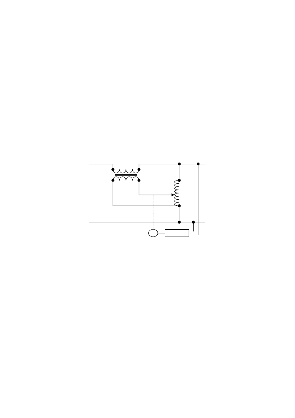
Input Output
Figure 1. Single phase regulator block diagram
As shown in figure 1, the only active component in the main power path of the voltage regulator is
the secondary of the buck‐boost transformer. This gives the regulator the advantage of being able to
withstand substantial current overloads.The variable transformer brushes, which are the most
vulnerable component in any variable transformer system, are completely isolated from overload
conditions by the buck‐boost transformer. Due to transformer inefficiency above rated design, the
amount of current that the buck‐boost transformer can induce across to its primary winding and into
the variable transformer circuit is dramatically decreased as regulator overload
current increases.
The controller monitors the regulator’s output voltage and then uses these feedback signals to
determine drive commands for the variable transformer motor interface circuit. The controller is
designed to adjust the motorized variable transformer to provide a +/‐1~2% or better output voltage
regulation over the entire input voltage range.
5‐ Functions Introduction
M
Controller
Buck-Boost transformer
Variable transformer